back to 'hardware'
| Pictures from visits:
December 2018 September 2022 January 2024 January 2025 | |
| Rack placement | 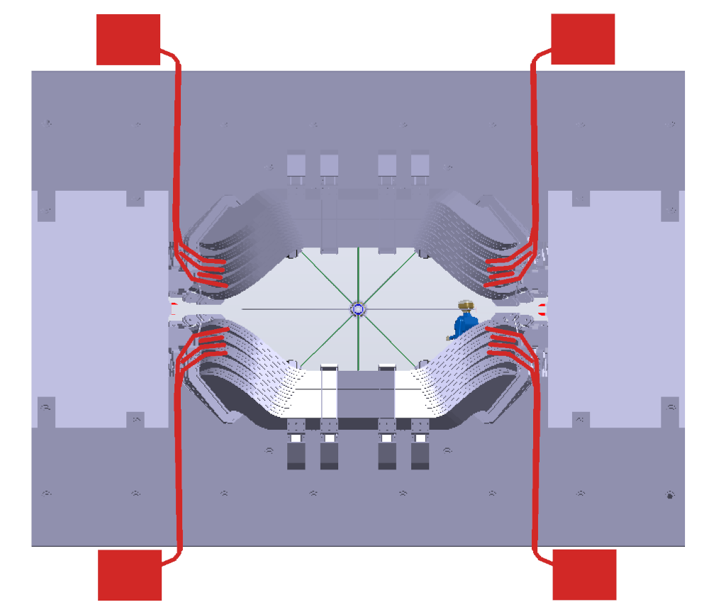
|
| Rails, frames and cable trays | 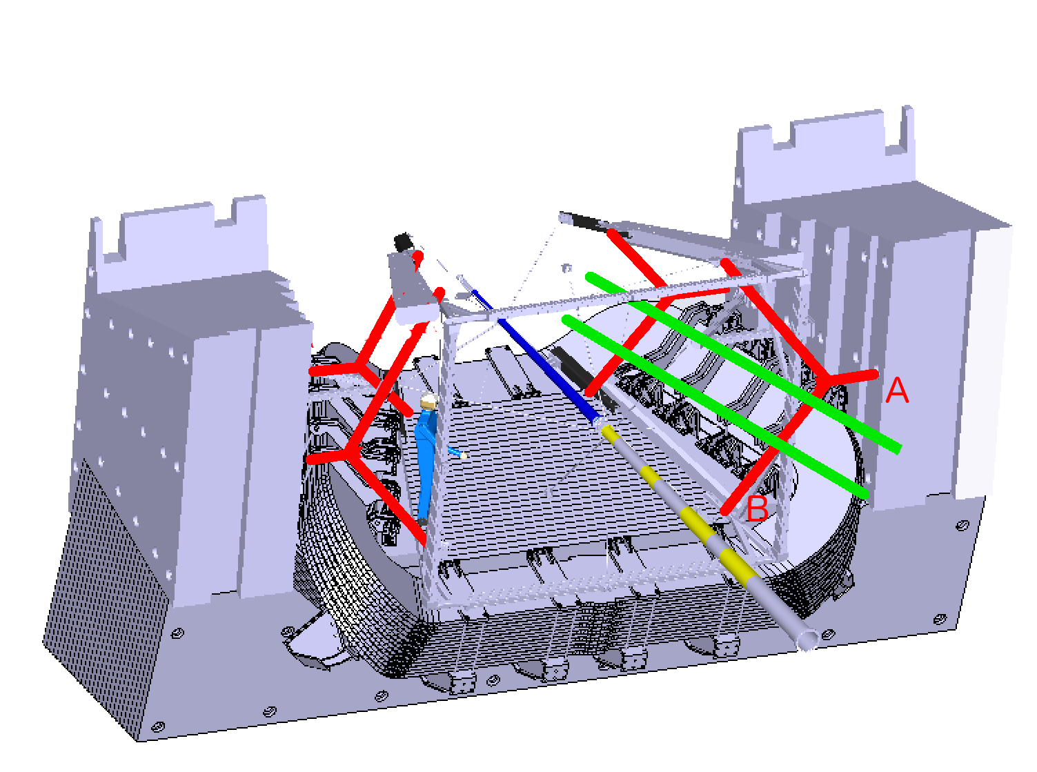
|
| WLS fibers and connectors | 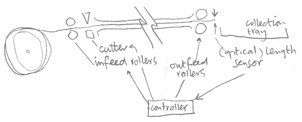
|
| Clear fiber ribbons and connectors | |
| Trays and connectors | 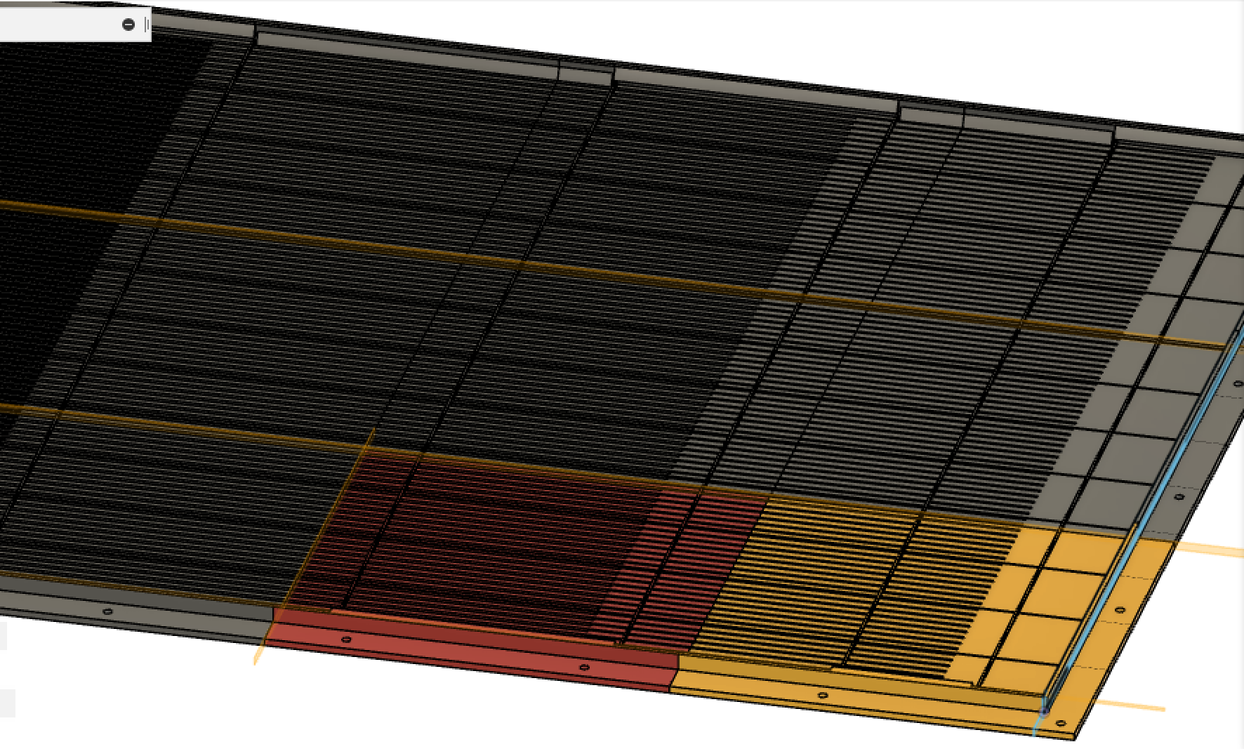
|
| Full-size mockup | 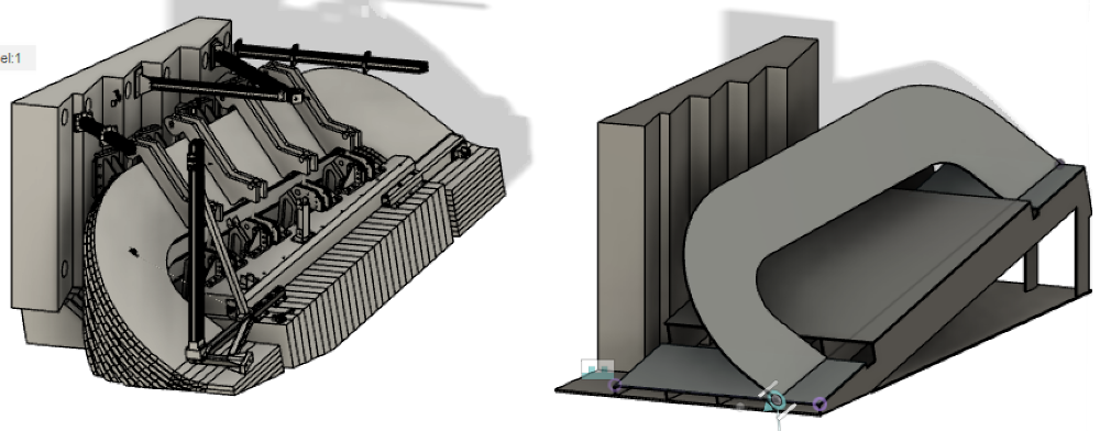
|
| Assembly timing test | |
New configuration (Oct 2024):
| 
|
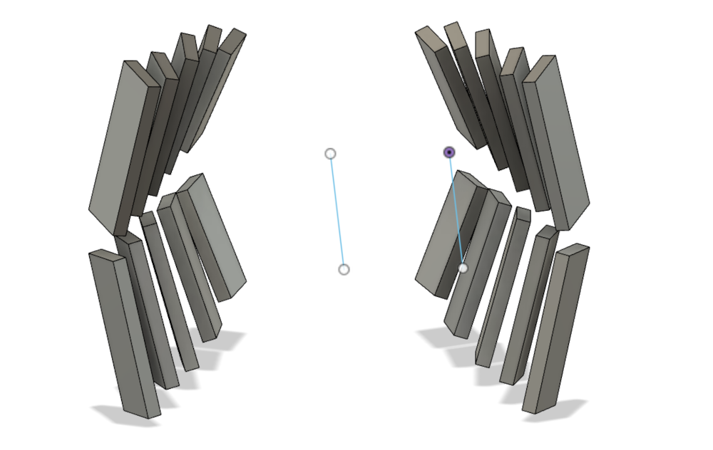
| Nicholas has run simulations to optimize the configuration. Here is the last one, with 9 panels per quadrant, rotated and tilted to optimize coverage, tracking (normal incident angles), and clearance from various structures. | |
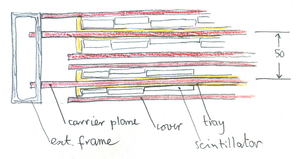
The panel edges are not yet defined, but they can consist of
rectangular Al tubing, 3mm wall thickness, and ~10 × 2 cm.
The central support panel of each pair of layers can have tabs that
fit into slots in the tube wall, and the cover panels can go all
the way to the tube, making a light-tight enclosure. (Nylon
nuts and bolts should then be black).
| 
|
| Here is a version of the master frame from back when the panels
were all in line, and parallel to the coil surface.
STEP files and other docs are linked here: | 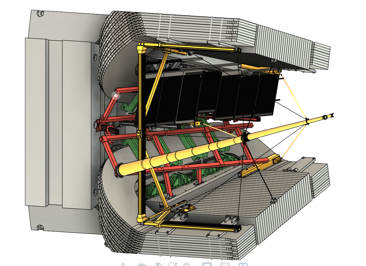
|
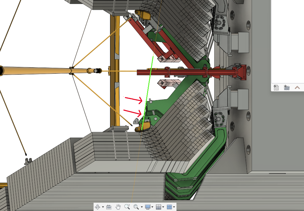
| The front face of the white beam and the blue line through the bracket tips lie in a plane tilted by 8.6°, and the beam is parallel to the central plane. It clears the first top green bracket, but bangs into the 3rd lower bracket. So we have to come out to clear both the lower and upper green brackets. | 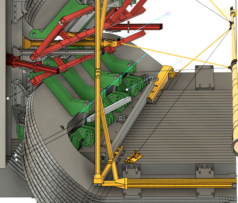
|
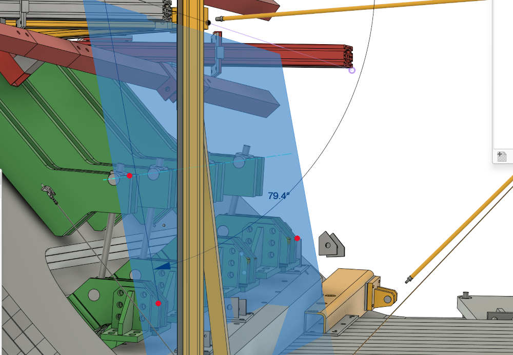
| New plane: here is a plane through 3 points, the top two on the
corners of the top brackets, and the lower one on the corner
of the last bottom bracket. Angle wrt vertical is 20.4°.
The other choice is to take 2 point from the bottom bracket and one from the top, for an angle of 10.6°. Much better. | 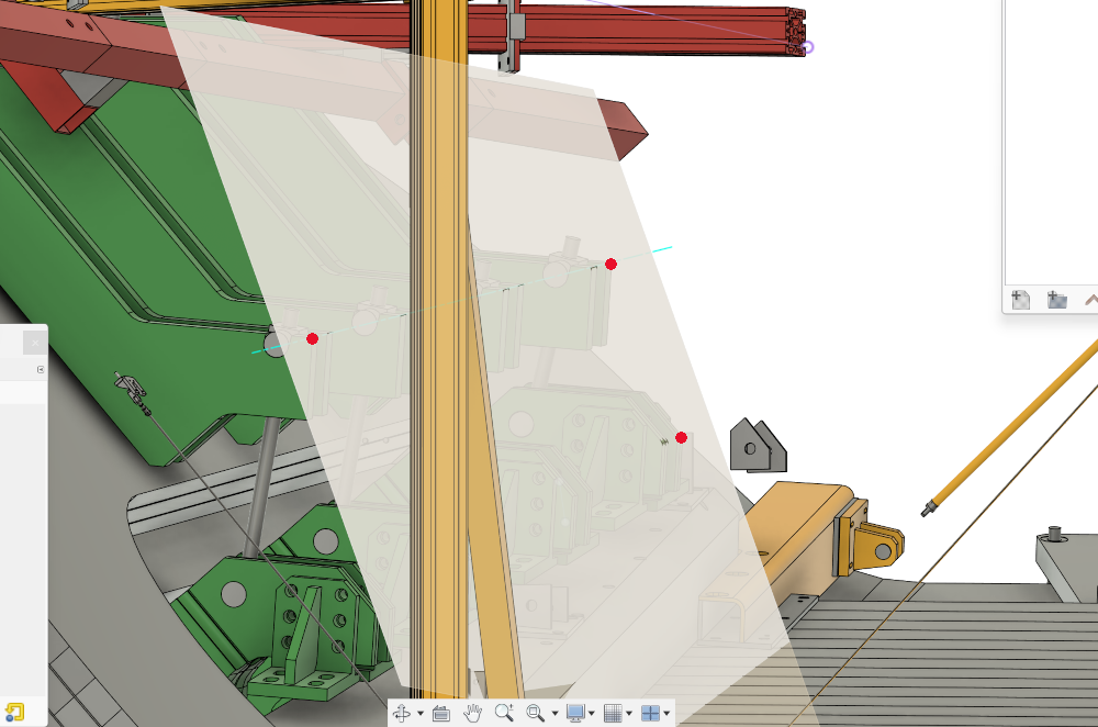
|
back to 'hardware'
