(1)
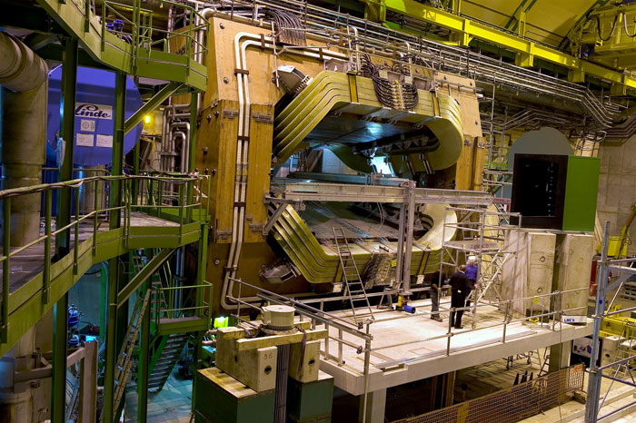
Pictures taken during a 2018 visit to the experiment
More pictures from September 2022
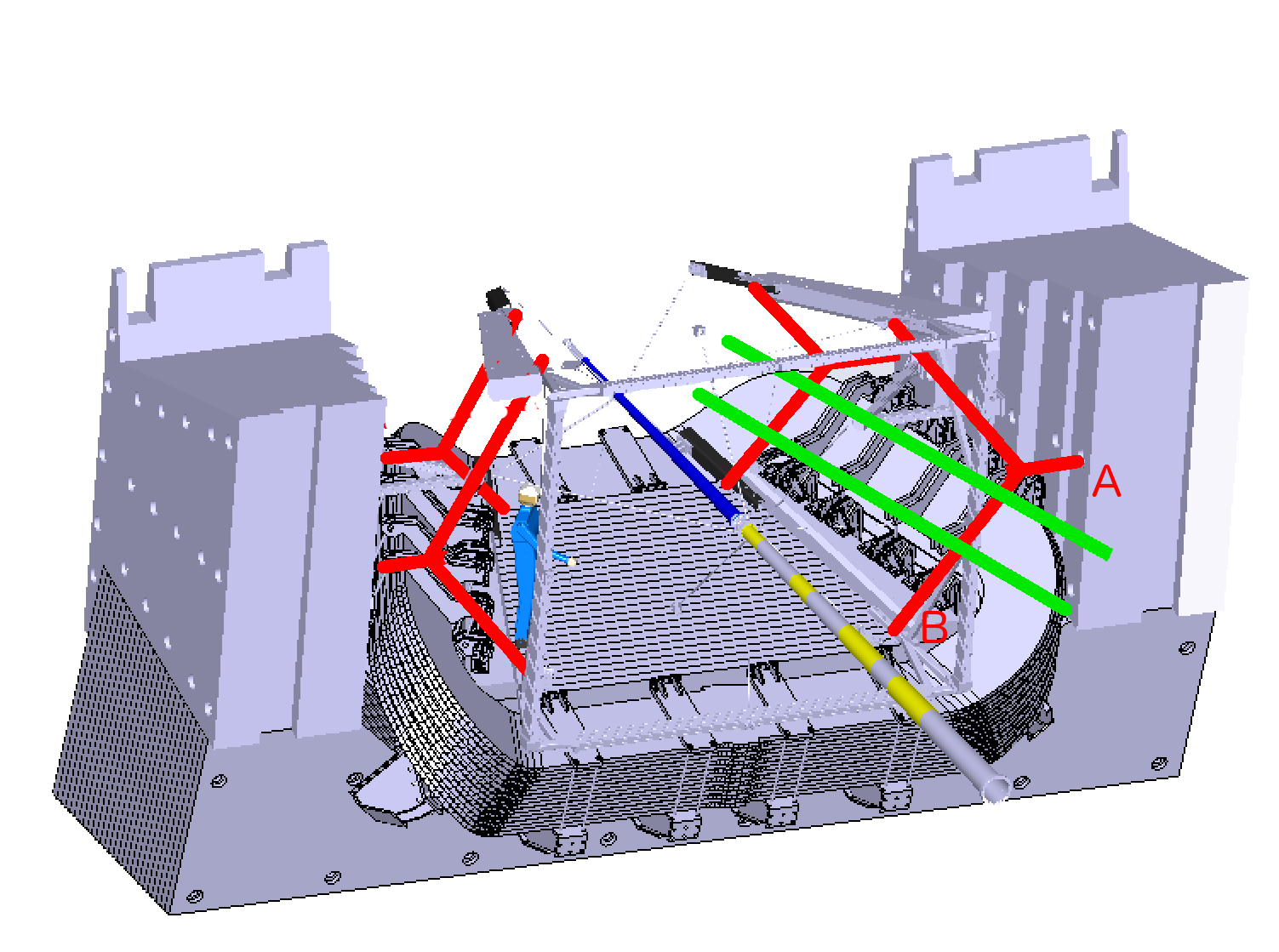
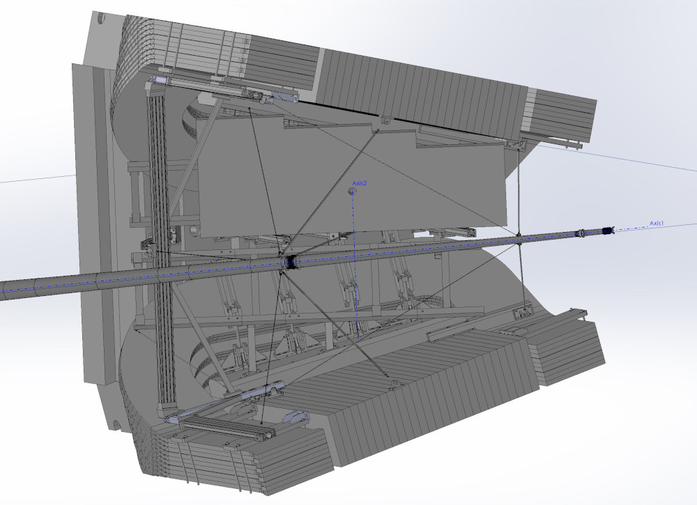
2018: Isometric front view (right) and top view (below),
from this EASM file.
A selection was converted to an EASM file.
The whole hall
Previous version of this page
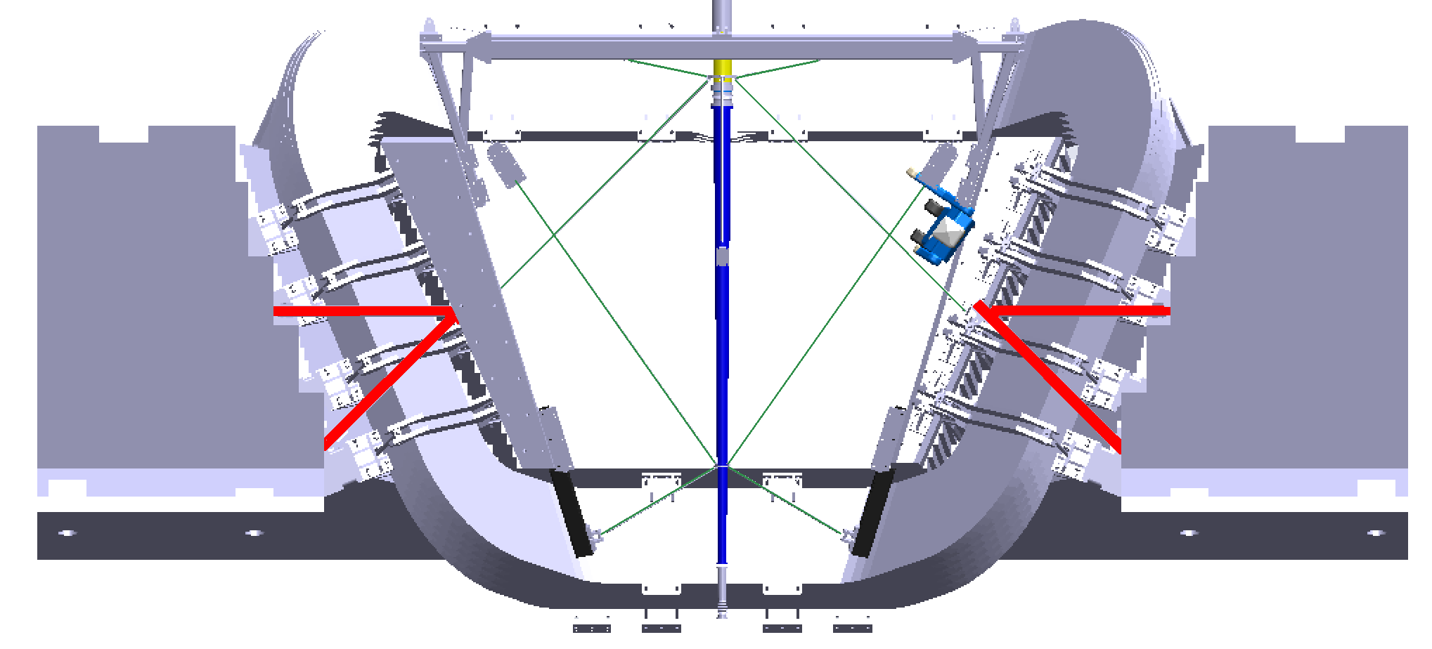
The diagonal wires (green) of the spider attach the front of the beampipe
to points near the front and the back of the magnet (both top and bottom).
The horizontal and vertical wires attach the back of the beam pipe to
points in the center (z) plane, as well as to the back. In red is a frame
where the horizontal wires attach.
| 
|
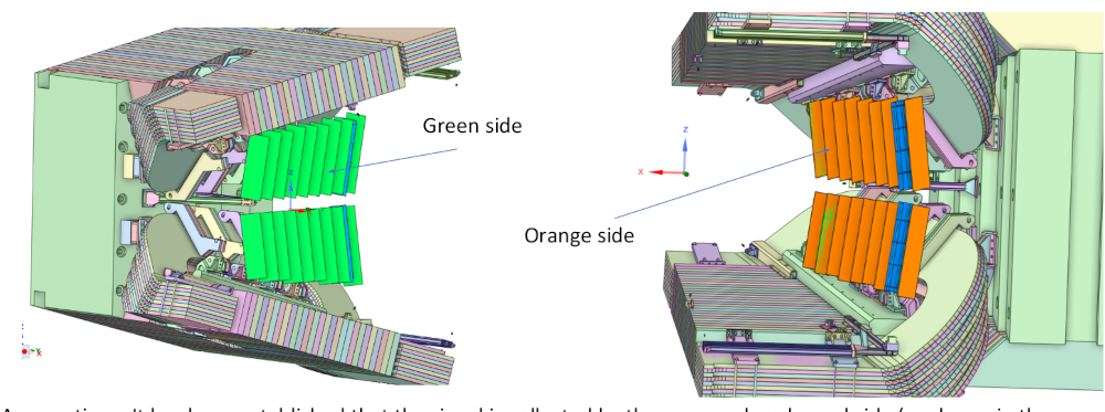
(2)
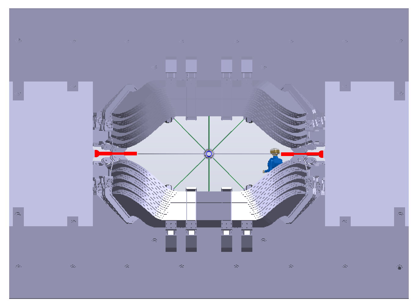
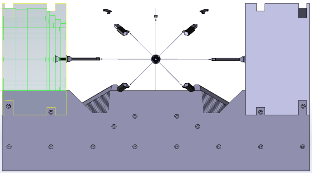
There are 4 bars (green), which appear to be part of the magnet poles.
These would make good attachment surfaces. However, the various spider frames
and points are not mounted from these bars. Are we allowed to mount to these
bars?
|
|
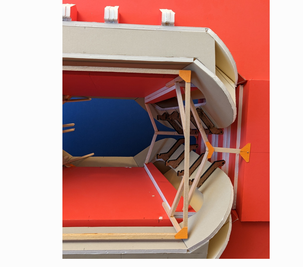
(3)
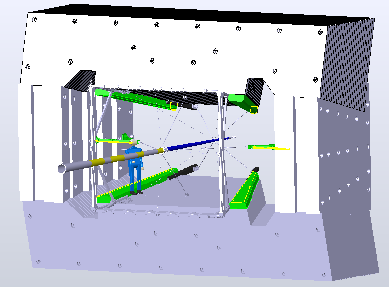
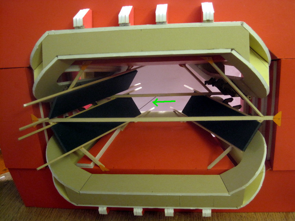
Top of the iron removed for clarity.
In red are Y-shaped brackets which are anchored
in three points: points A are on the vertical walls, on the horizontal
center plane. Points B are near where the anchor points for the beam
pipe spider are. The angled sections are parallel to the magnet coil face.
The green bars are mounted on the red brackets and are parallel to each other.
These are rails, along which the scintillator chambers can be slid into
place.
| 
|
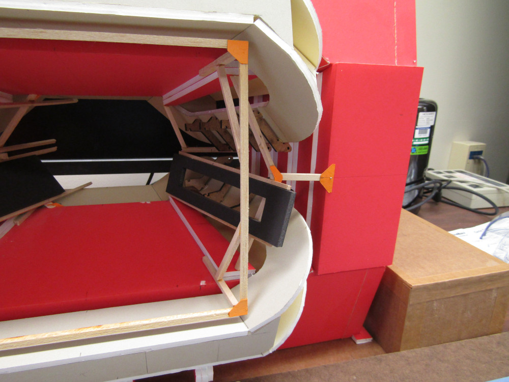
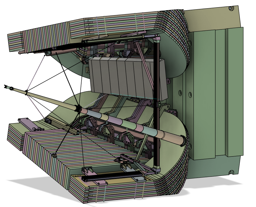
(4)
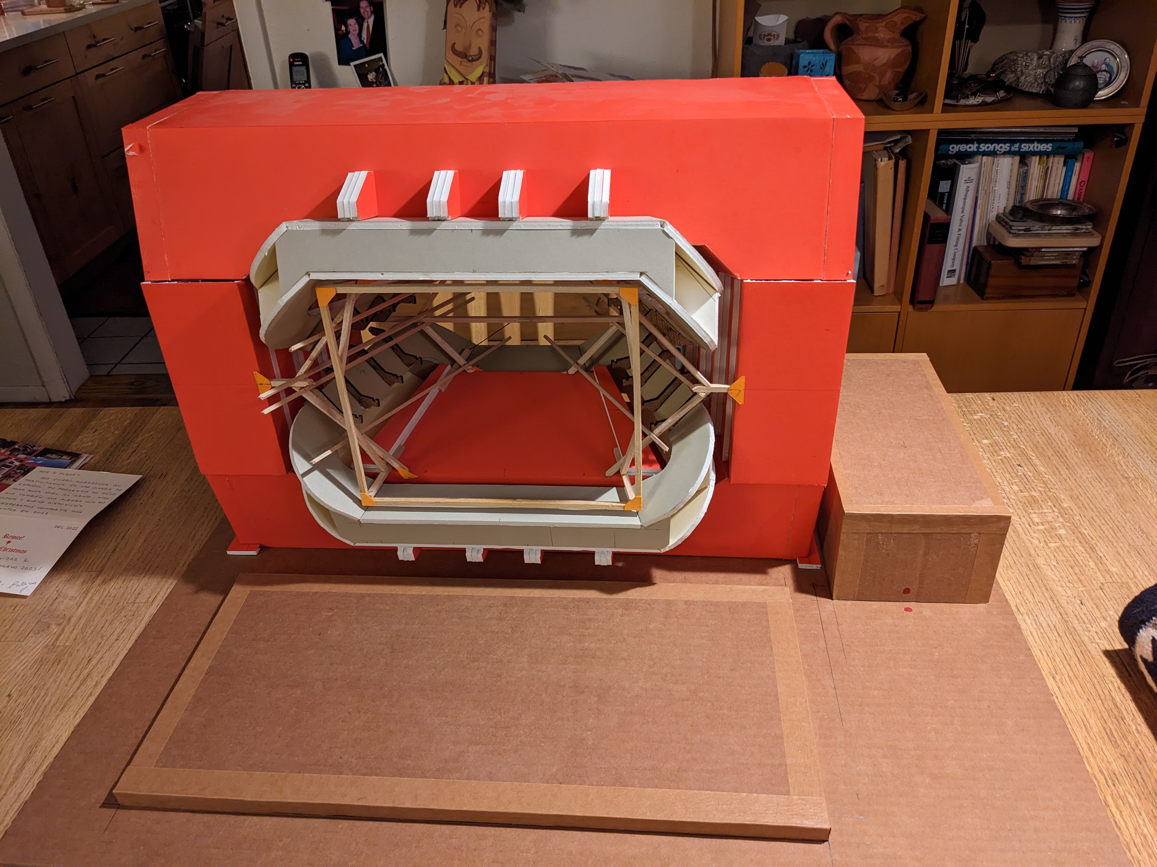
Three chambers (black, measuring 1m high and 4m long), installed. The green arow points to one arm of the
spider that holds the beam pipe near the front.
The spider wires in the horizontal and vertical planes do not interfere. There
are also diagonal wires going from the forward beam pipe attachment ring, and
are anchored further towards the back. These are also cleared.
|
|
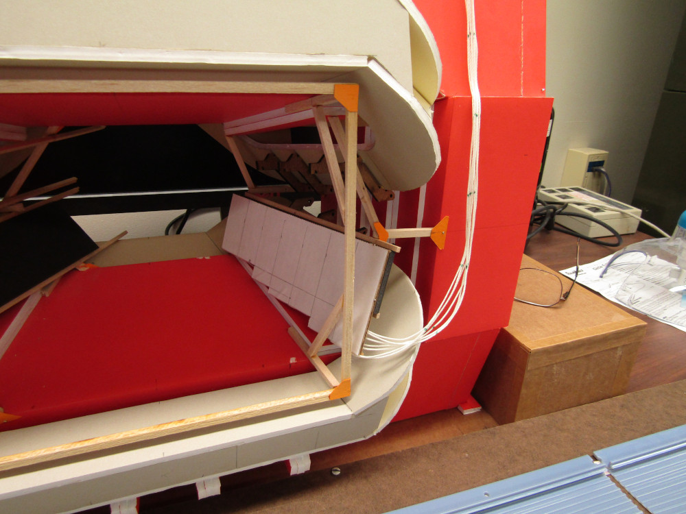
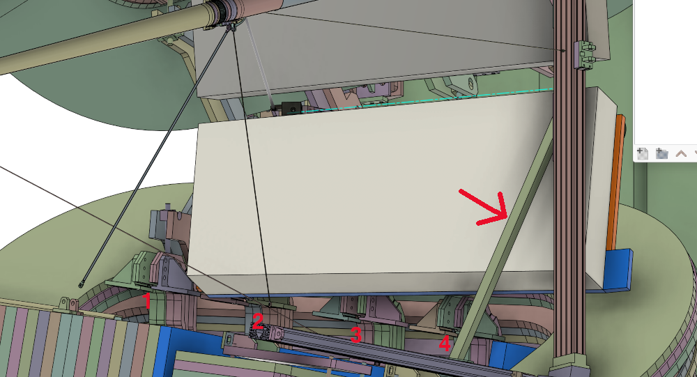
(5)
2022: Work resumes on the installation design.
There is a
possibility to have taller (>1m) panels at the wider end of the magnet.
How tall? I added to the model the frame that holds the wires
that support the beampipe, and the braces, since the braces
limit how tall panels can be.
| 
|
(6)
| 
|
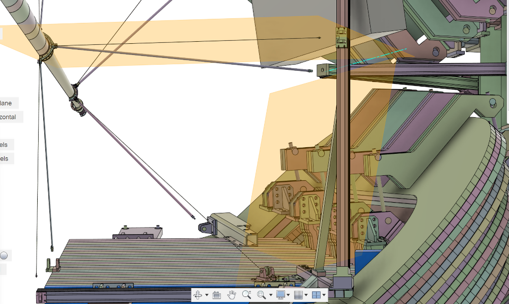
(9)
The optimal tilt angle is when a normal to the plane intersects
the beam axis. This is 74° wrt the horizontal plane. (Eric)

|

|
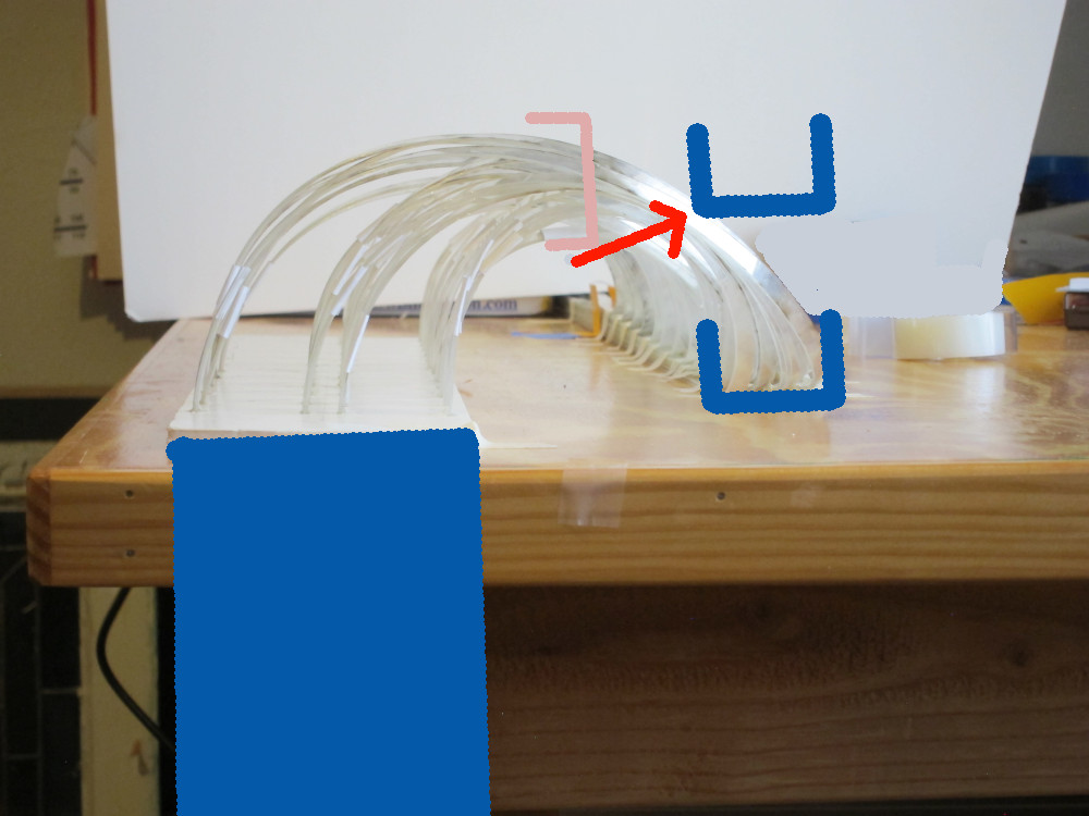
(10)
The 74° frame just clears the magnet brackets, and
the brace of the spideweb frame limits the vertical space
available for the detector panels
| 
|
(11)
krakow_frames_feb23.ppt
| 
|
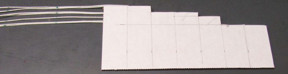
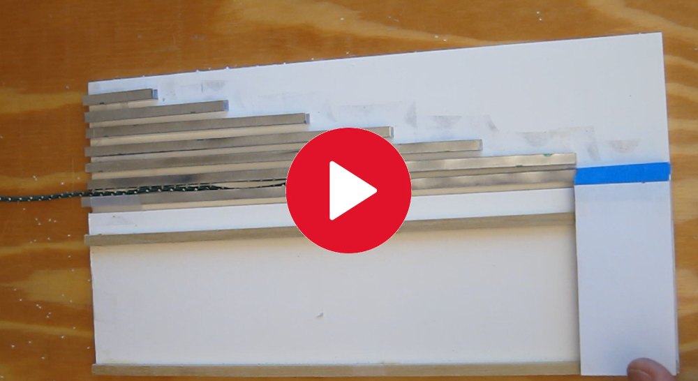
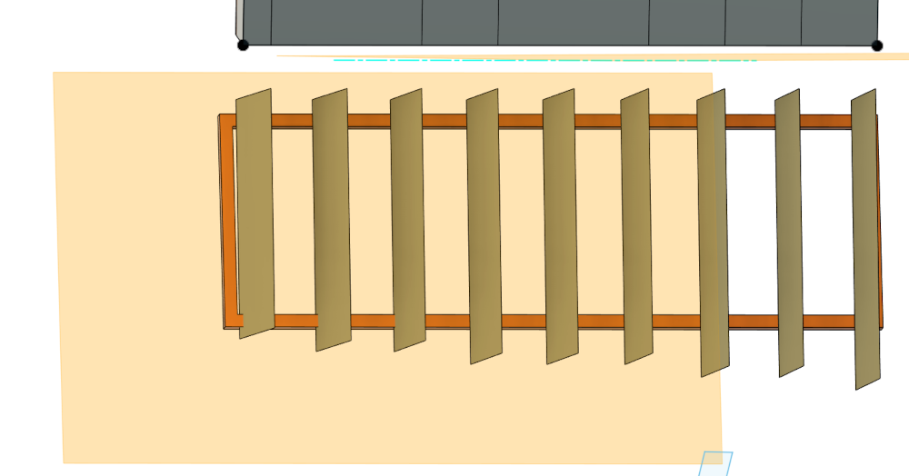
(12)
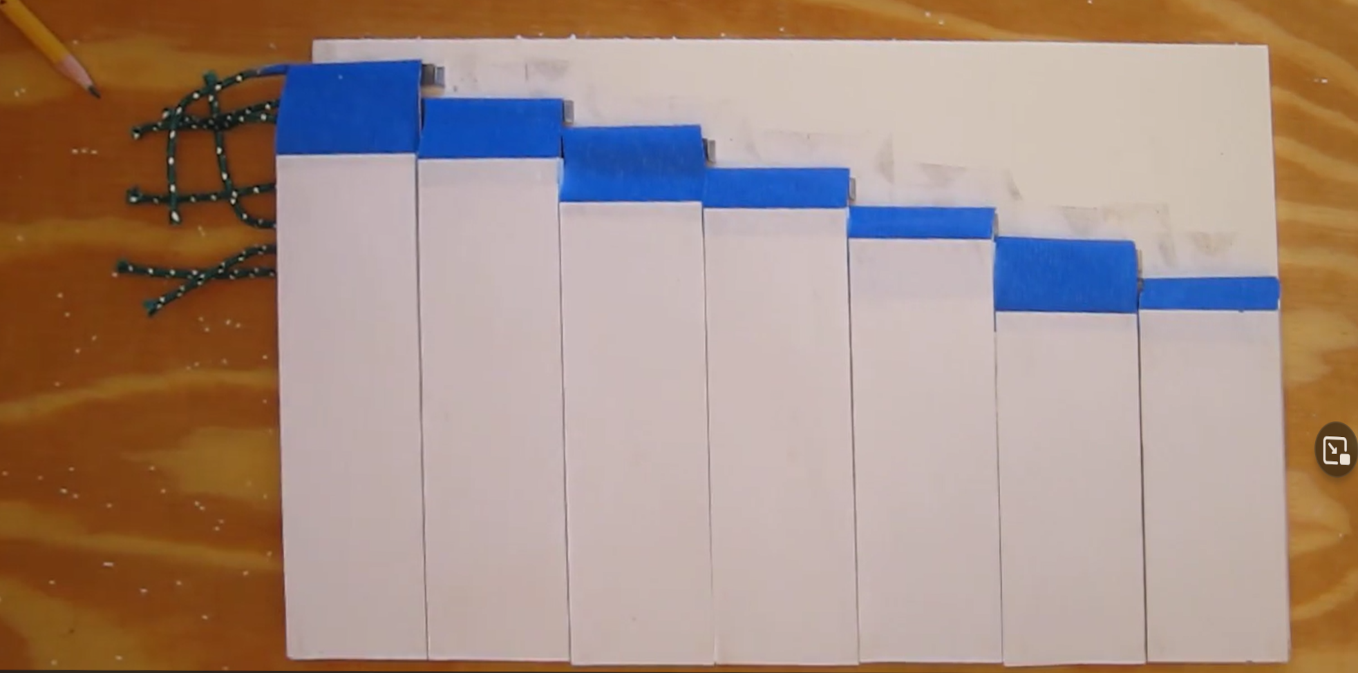
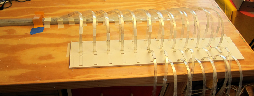
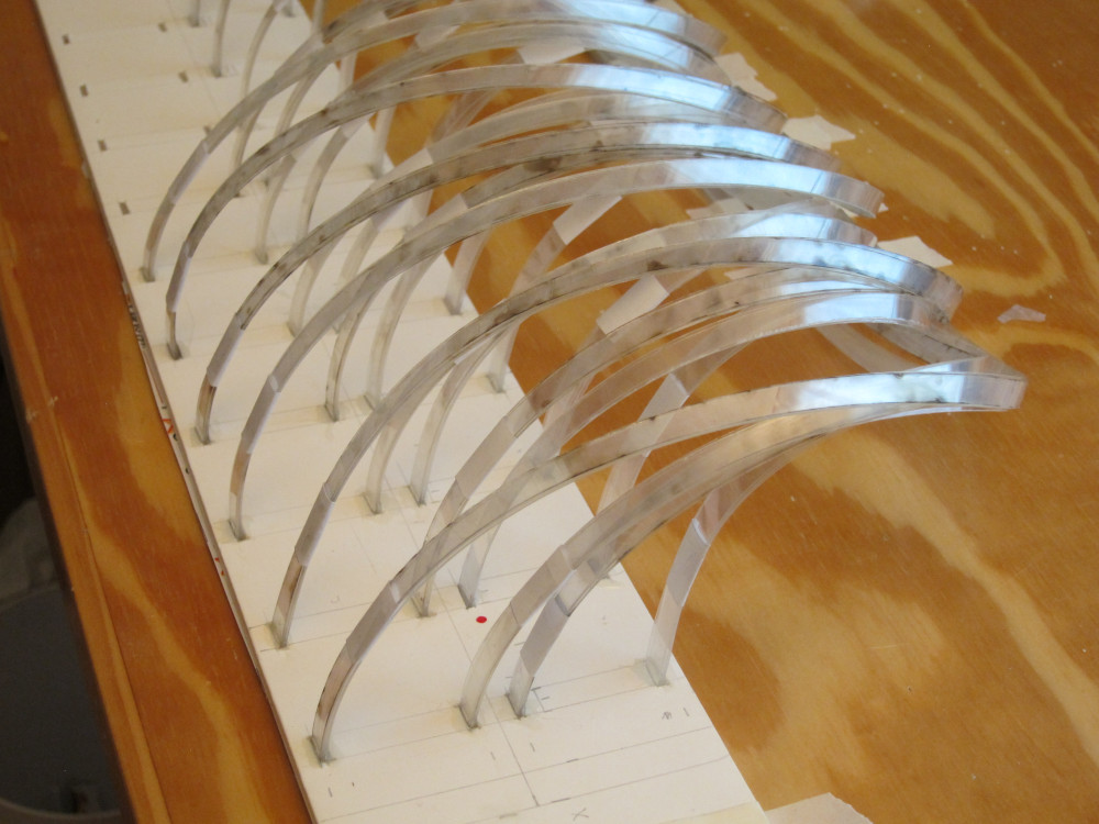
7 panels (100,100,120,130,130,145,145) with fibers coming off the
edges away from the center plane. The marks on the string are at 1m
intervals
On the back, the fiber bundles can travel straight to the downstream
end
| 
|
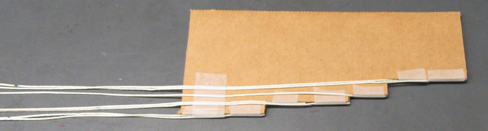
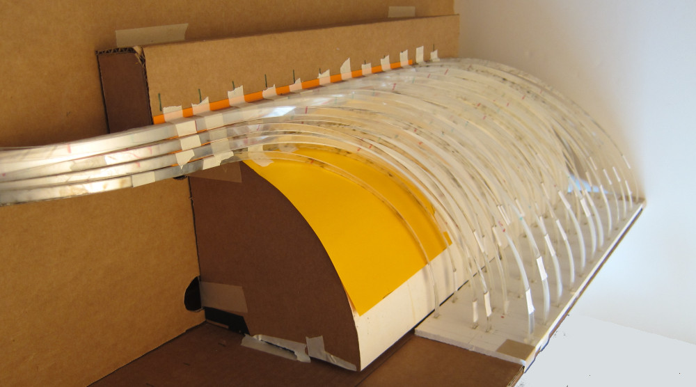
(13)
The black panel is 90×350cm, defined approximately by the
constraints on the rails at the narrow end of the magnet
| 
|
(14)
Panels mounted onto the rails. Here, the fibers are routed to the
top of the magnet. It takes a little over 6m from the panel exit to
the top edge of the magnet. Add to that the distance to the individual
panels (0.5 - 3.5m) plus the distance from the magnet edge to the
rack, which means the longest fibers in the system are ~12m long
(3m less for the top quadrant).
| 
|
(15)
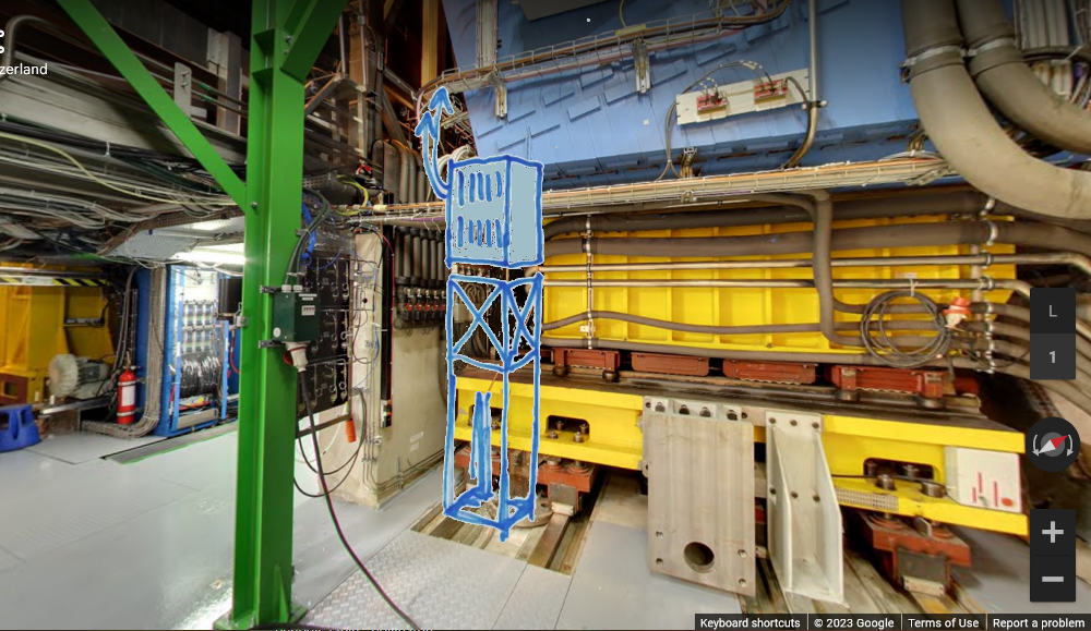
There is space below the magnet:
Picture from the
virtual walk-around →
(Mar 23 note: this is an old view, there is more stuff there now)
| But the shortest distance would be if the crates are on top and below like this:
|

|
| 
|
(16)
Watch how I install the panels:
| 
|
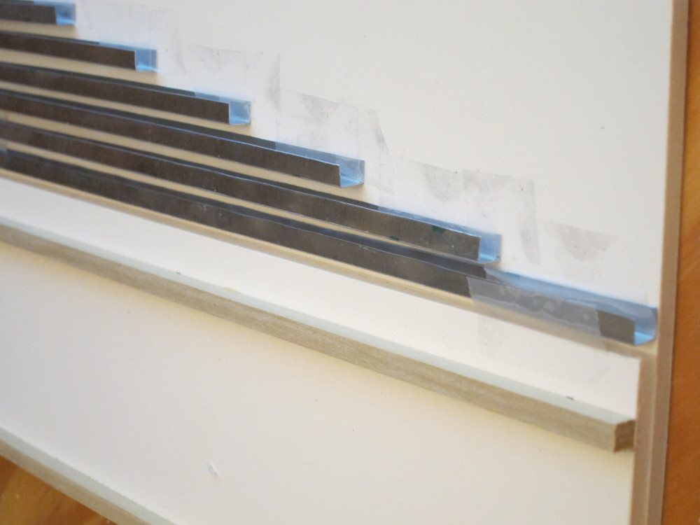
(17)
There is a set of trays (in this 10:1) model, they are 6×6cm),
one for each panel. The wood bar is one of the panel rails.
| 
|
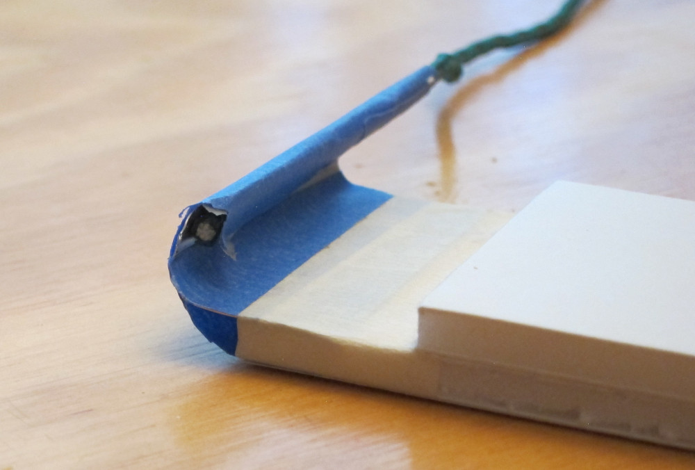
(18)
On the top of each panel, a rigid structure (blue) guides the
fiber ribbons up and over the lip of the cable tray.
How big is this bundle of fiber ribbons? Each panel has
4(pairs of scintillator blocks) ×
12(blocks wide per layer) ×
4(layers per panel)
ribbons, each 1×8mm in cross section (
see here),
for a total cross section of 15.36cm2, or about
4×4cm2 minumum.
| 
|
(19)
How big are these blue structures? At the end of the nominal panel
end (100 - 145cm), about 12cm are needed for the connectors plus ribbon strain
relief. Beyond that the ribbons curve up and over into the trays,
here about 10cm up and 10cm over (perpendicular to the unit plane).
mylar_80cm laser cut file
Here is a 1:1 mockup of the end of a module (50×10cm),
with 4×4×12
mylar ribbons coming out. How to route these 192 ribbons?
| 
|
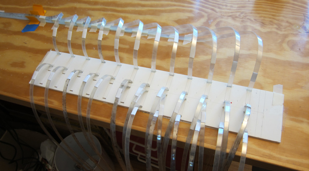
(20)
Next layer goes over the top
| 
|
(21)
The ribbons curve and twist such that the surface that faces
left in this picture end up facing down in the cable tray.
| 
|
(22)
The module (blue) is ~10cm wide, and the position of the cable
tray is determined by the minimum bending radius of the fibers, here
about 10cm. The next tray (see (17) above) has to clear the
fibers, and here it
is sketched in ~6cm above the lower one.
| 
|
(23)
Fiber ribbons at Saint-Gobin, which states "The typical
bend radius is 30-40 times the diameter of the fiber", which would be
1.5-2cm in our case.
An email from Steven Robare says "For [0.]5mm it is 10cm radius".
Another link about minimum bending radius:
"the bending radius of fiber should be more than 150 times the diameter of the fiber cladding". So for our 0.5mm fibers, this would be R>7.5cm, so to be safe, let's use 10cm radii. (In the pictures above, the
radius is 5cm).
| 
|
(24)
With a bending radius of 10cm we really need to conserve space.
Here the cable tray is rotated 90° (but the bending radius has not been
changed yet).
| 
|
(25)
Based on (23), I made a 17.5-cm radius quarter-tube. Ribbons run
on the surface, and follow the orange cutout which also has a 17.5cm
radius. Thus the ribbons reach the horizontal before going 90%deg;
in the xy plane.
| 
|
(26)
Based on (26), I made a 17-cm radius quarter-tube. Ribbons run
on the surface, and follow the orange cutout which also has a 17cm
radius.

| 
|
(27)
Given a minimum bending radius (here 17.5cm), this is the minimum
space needed. If the orientation of the cable tray does not matter,
the tray can in principle be moved along the green arc.
| 
|
(28)
ppt presentstion, Lukasz Felkowski 17 Feb 2025
| 
|
(29)
I got the step file 25_02_2025_model_v2.stp....
|
|
(30)
I constructed 2 planes (yellow), one tangent to the tips of the magnet
support bracketes, which is therefore as far back as possible,
and the other a central horizontal plane.
The bright blue line is the intersection btween the two planes.
| 
|
(31)
On this plane I constructed a master frame out of 50x50 mm 80/20.
The horizontal bars are spaced so that they fall 50mm inside of the
smallest panel, and horizontally the frame protrudes a bit beyond
panels 1 and 9.
The frame is parallel to the blue line, which is horizontal.
|
|
(32)
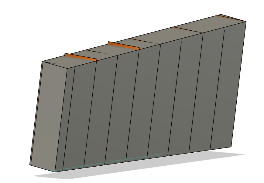
Now I need to move the panels onto this frame. Rather than trying this
directly, I constructed a box enclosing the top set of panels.
This volume holds the panels. Dimensions are
	thickness  292 mm
	length    2500 mm
	height 1  1150 mm
	height 2   950 mm
| 
|
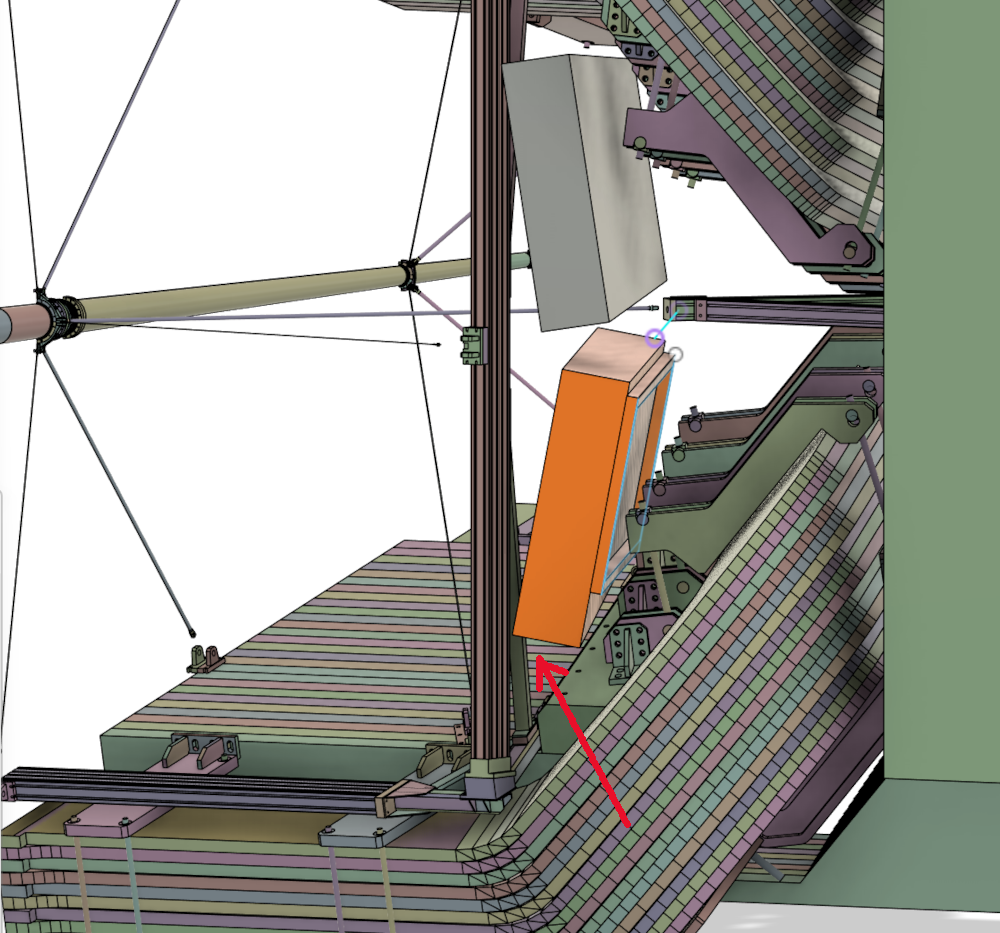
(33)
The top box was the one used to capture all panels. The bottom
box is a copy mounted onto the master frame.
Note 1: This box does not interfere with the vertical post of the
spider frame. However, there is a few mm interference with the
diagonal brace of this post.
Note 2: The frame does not interfere with the magnet brackets (by
design), but it could be moved even further back, since the frame
beams fall in between the brackets.
| 
|
(34)
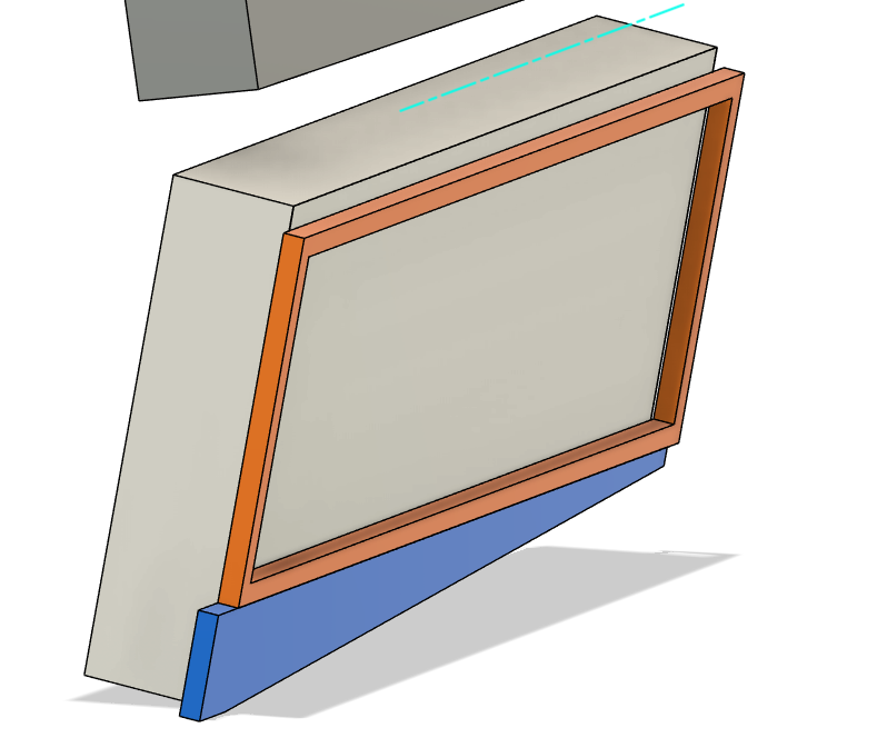
Here are the panel components: master frame (orange), panel
volume (grey) and fiber bundles (blue)
Lets look where the interferences are
|
|
(35)
There is no problem with the upper brackets - there is 80 mm
clearance there
|
|
(36)
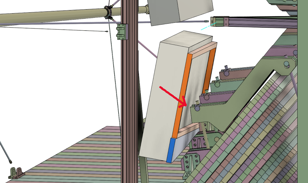
For the bottom brackets, #1 doesn't matter, and #4 is below the
(blue) fiber bundles. The spider frame brace (arrow) is our problem.
Bracket 3 is our constraint, and so if we pivot the panel box around
bracket 3 by a degree or so, we can completely clear all interferences.
|
|
(37)
|

|