LV/BV distribution

The power distribution for the hodoscopes is split into three parts: a master box that controls everything, six power boxes that generate the low voltage and bias for the hodoscopes, and the hodoscope boxes themselves. See links on the right for descriptions of the individual elements.
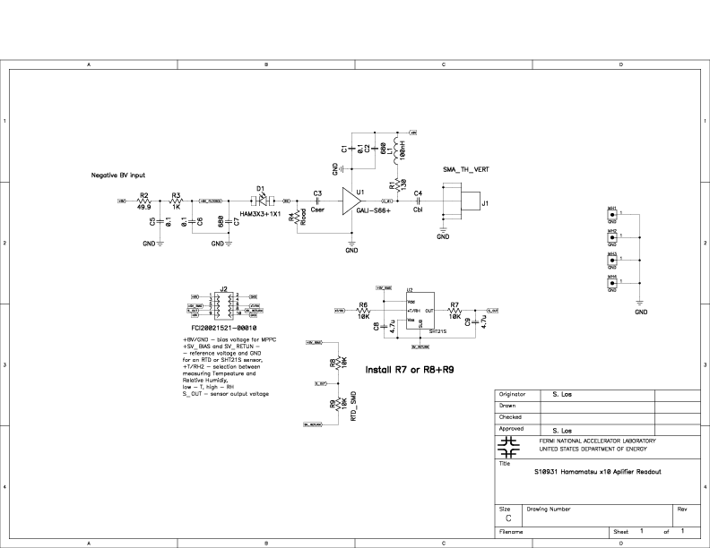
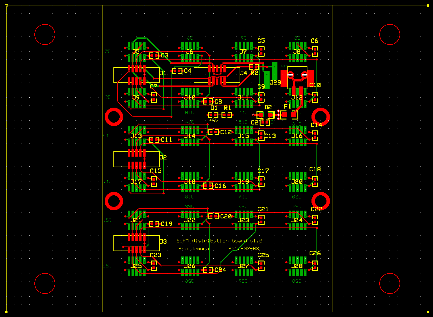
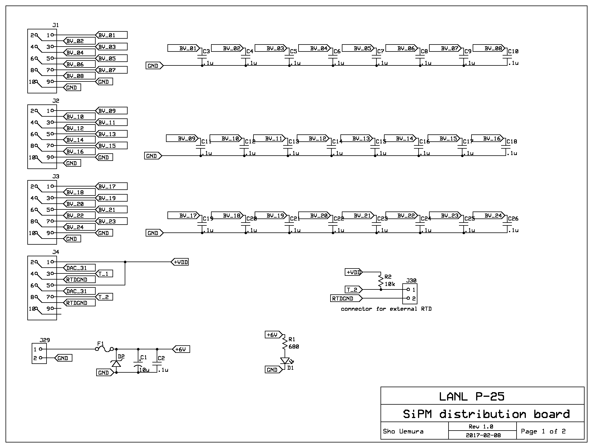
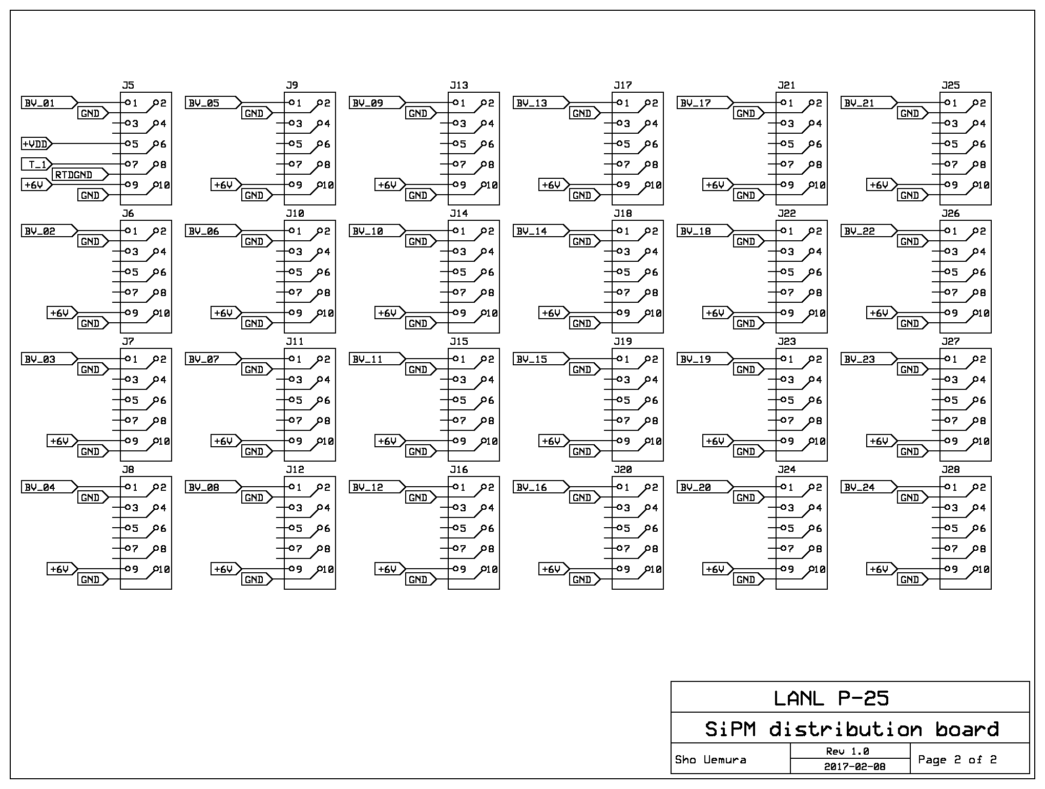
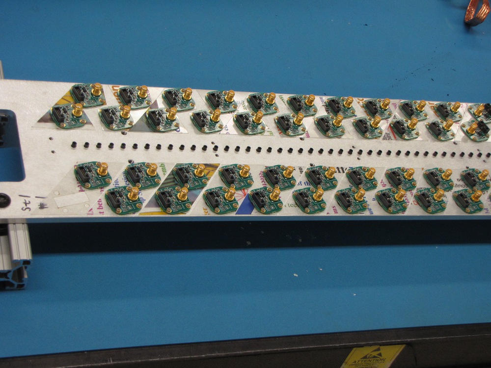
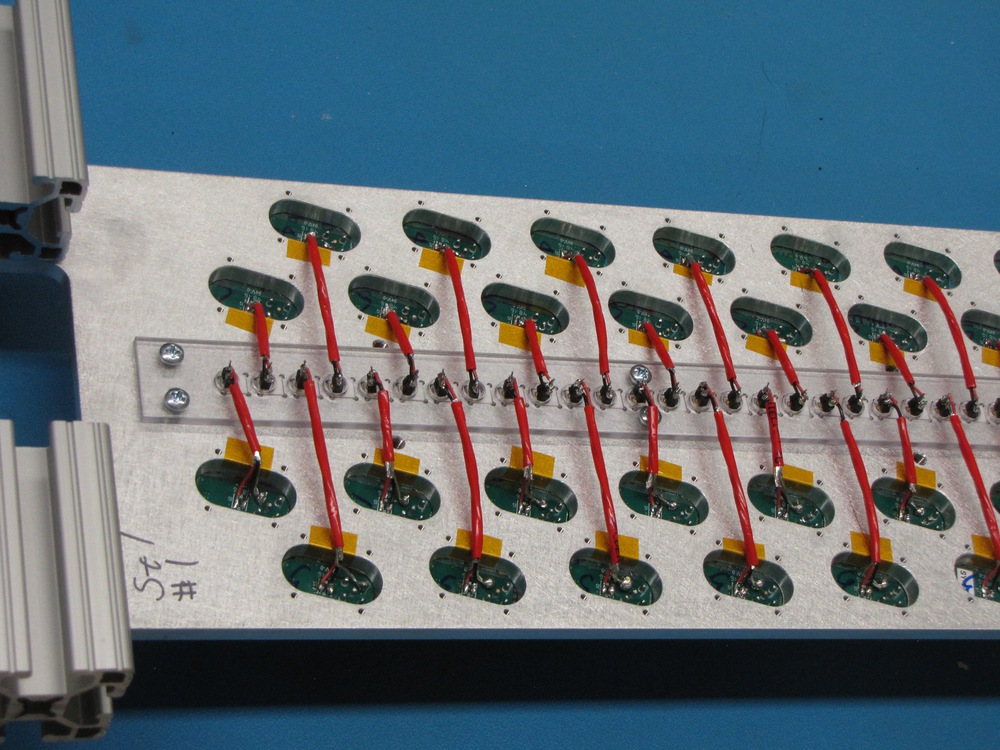
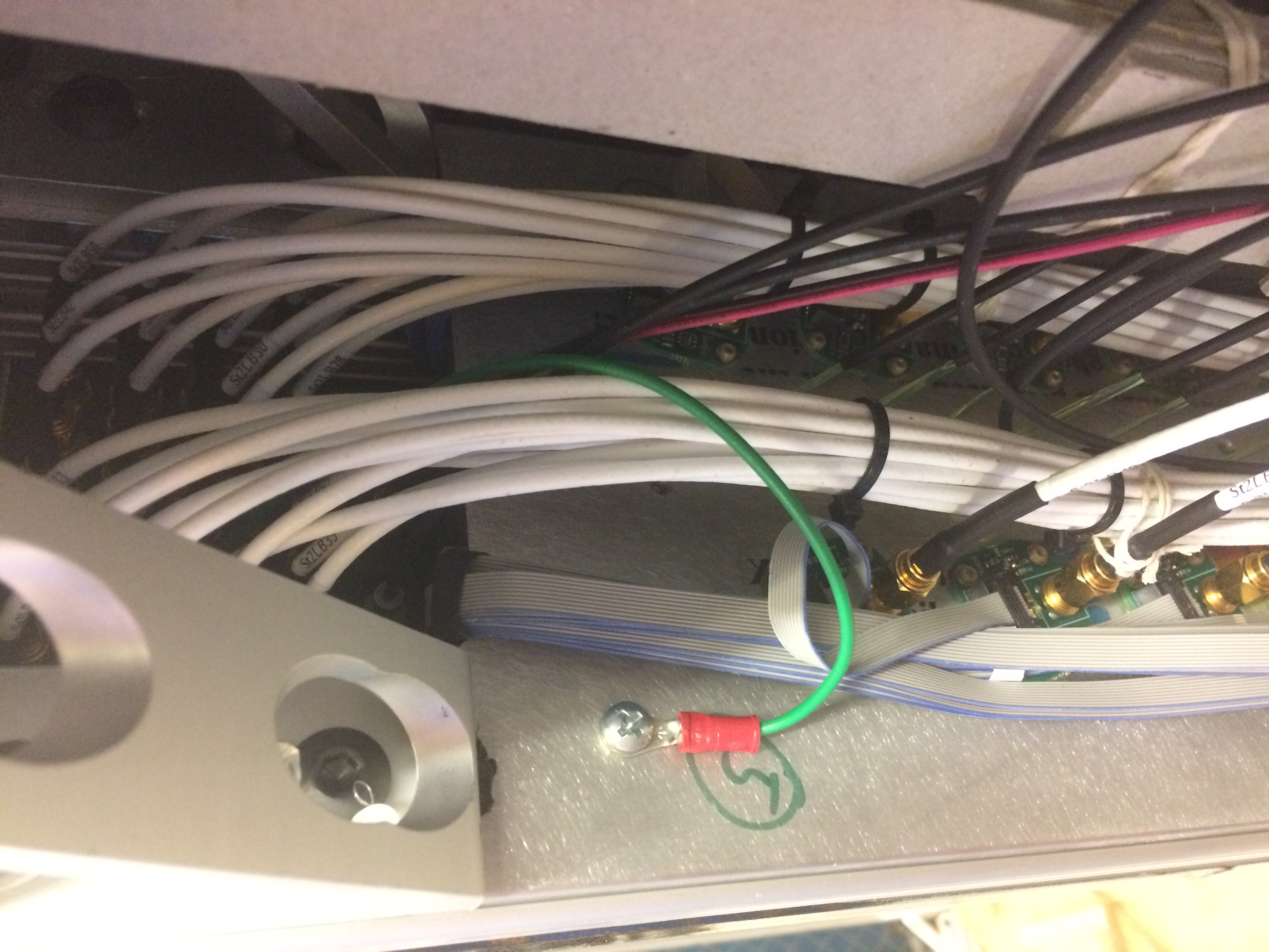
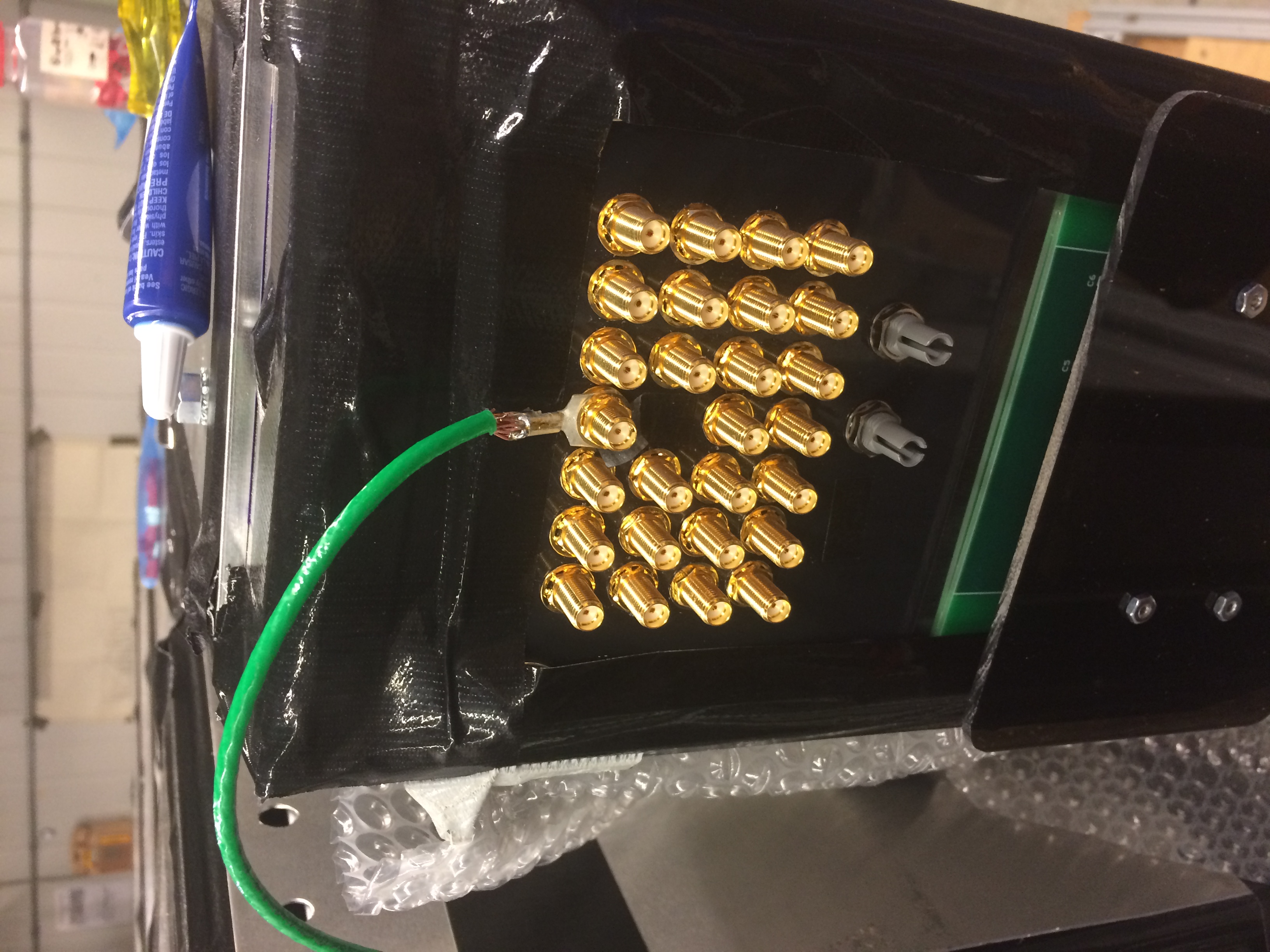
Electrical safety and system diagrams

Power dissipation of hodoscope boxes

Each detector box has either 80 channels (station 1 quadrant) or 50 (station 2 quadrant).

Each channel comprises an SiPM and a preamp. In addition, each box has either 4 (station 1 quadrant) or 2 (station 2 quadrant) distribution boards.

The SiPMs operate at bias voltages of between 53 and 56 V. The bias current is the sum of the beam-induced photocurrent and the constant dark current. The photocurrent is conservatively estimated at 10 microamps per channel for the highest-rate channels. The dark current will increase with irradiation, but is not expected to exceed 50 microamps per channel. Therefore, the maximum SiPM power dissipation per channel is 3.6 mW.

The preamps are class-A amplifiers with an operating voltage of 6V and a bias current of 16 mA, for power dissipation of 100 mW per channel. Because of the class-A topology the power dissipation does not depend significantly on the hit rate.

The distribution panels carry both the 6V low voltage for the preamps and the individual bias voltages for the SiPMs. The only power dissipated by the distribution panel is a 5 mA LED.

From the above, the total power dissipation of each quadrant is estimated at 8.3 W for station 1 (80 channels), and 5.2 W for station 2 (50 channels).

Circuit protection

All power in the system is supplied by DC power supplies built into the master box and power boxes. The AC inputs to these supplies are protected by fuses in the power entry modules. These supplies have short-circuit protection.

The master box supply (+5V) is rated at 3 A. All wiring powered by the master box is a minimum of 24 AWG, except for the long twisted-pair cable (Category 5) that carries I2C signals, which is 26 AWG; this cable is protected by a 250 mA polyfuse on the master board.

The power box supply (+9V) is rated at 6.67A. All wiring powered by the power box is a minimum of 20 AWG, except for the bias voltages and the preamp power, each discussed below.

The bias voltages are generated by a DC/DC switching supply inside the power boxes. This is set to output +100V and has short-circuit protection, with a maximum output power of 5W (so the output current is limited to 50 mA). Bias voltage is carried by 24 AWG wire inside the power boxes. The control boards regulate the bias voltage for individual channels using linear regulators with a maximum output current of 100 uA, and these voltages are sent to the hodoscope boxes on 30 AWG ribbon cable.

Inside the hodoscope boxes, the preamp power (+6V) is distributed on 30 AWG ribbon cable. The 6V input of each distribution board is protected with a TVS zener diode and a PTC polyfuse. The polyfuse is rated at 1.1A, which is within the ampacity of the preamp ribbon cables. There is redundant protection on the control board inside the power box: the +6V is created by an external transistor, and there is a 1.25A fuse on the +9V supply to that transistor.

Grounding

The master box and power boxes are standard 1U rackmount boxes, which are grounded through the AC line plugs. On the hodoscope boxes, the distribution boards are grounded through both the +6V supply and the bias cables; the preamps are grounded to the distribution boards and to the discriminators in the DAQ. The boxes themselves are grounded through a separate path: the preamp plate is grounded to a lug in the patch panel, and this lug connects to a grounding braid that runs to the DAQ rack.
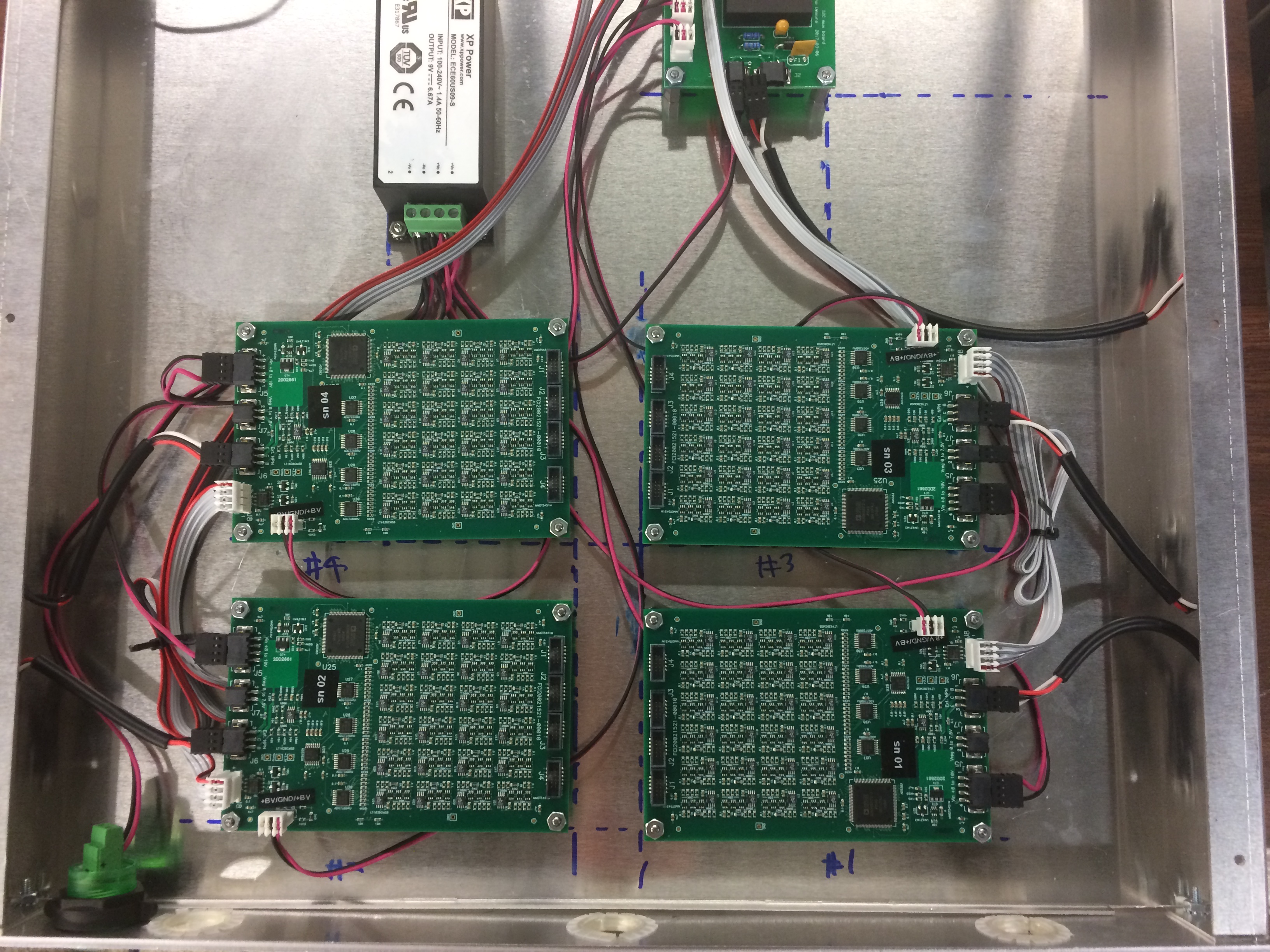
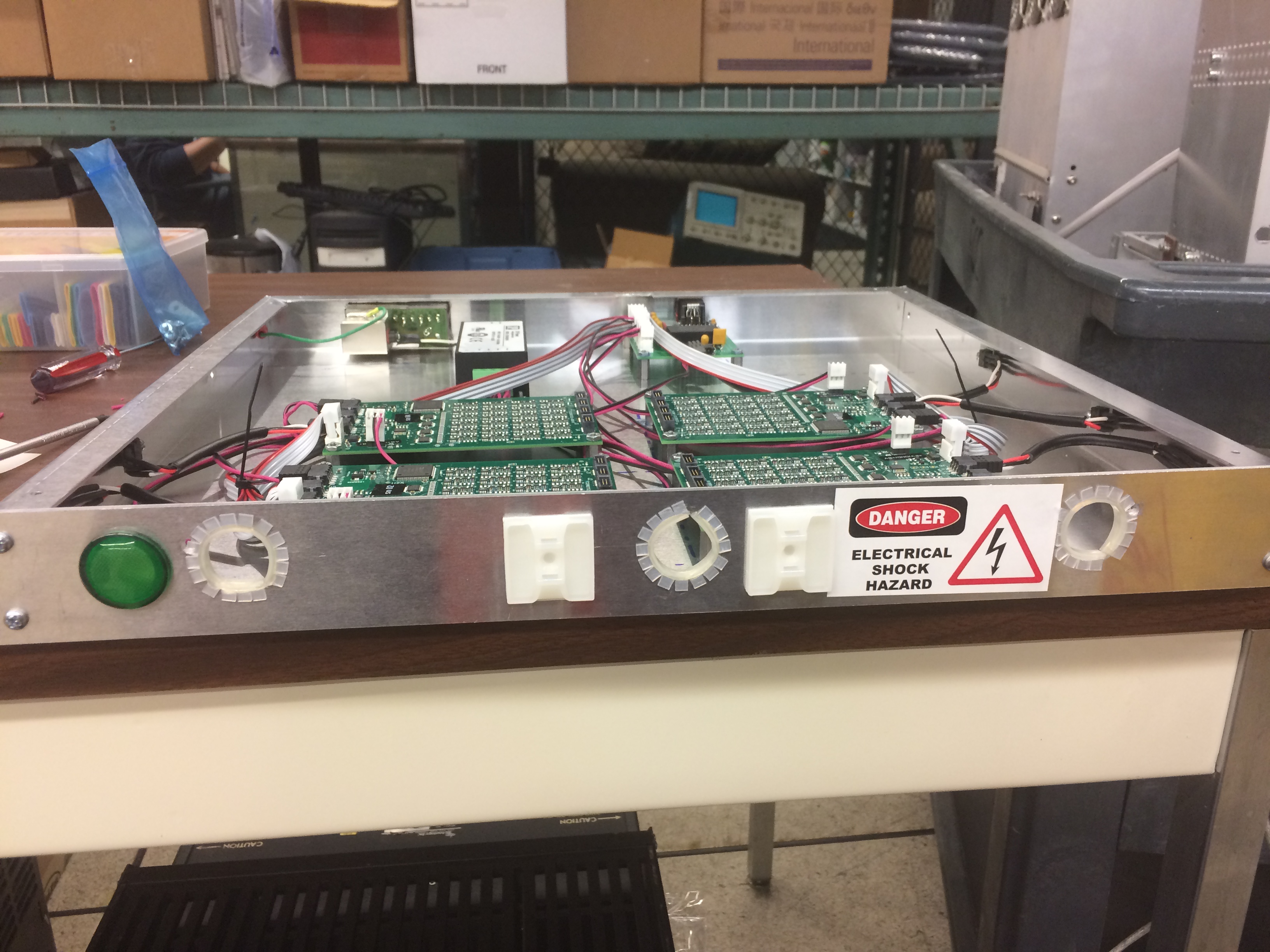
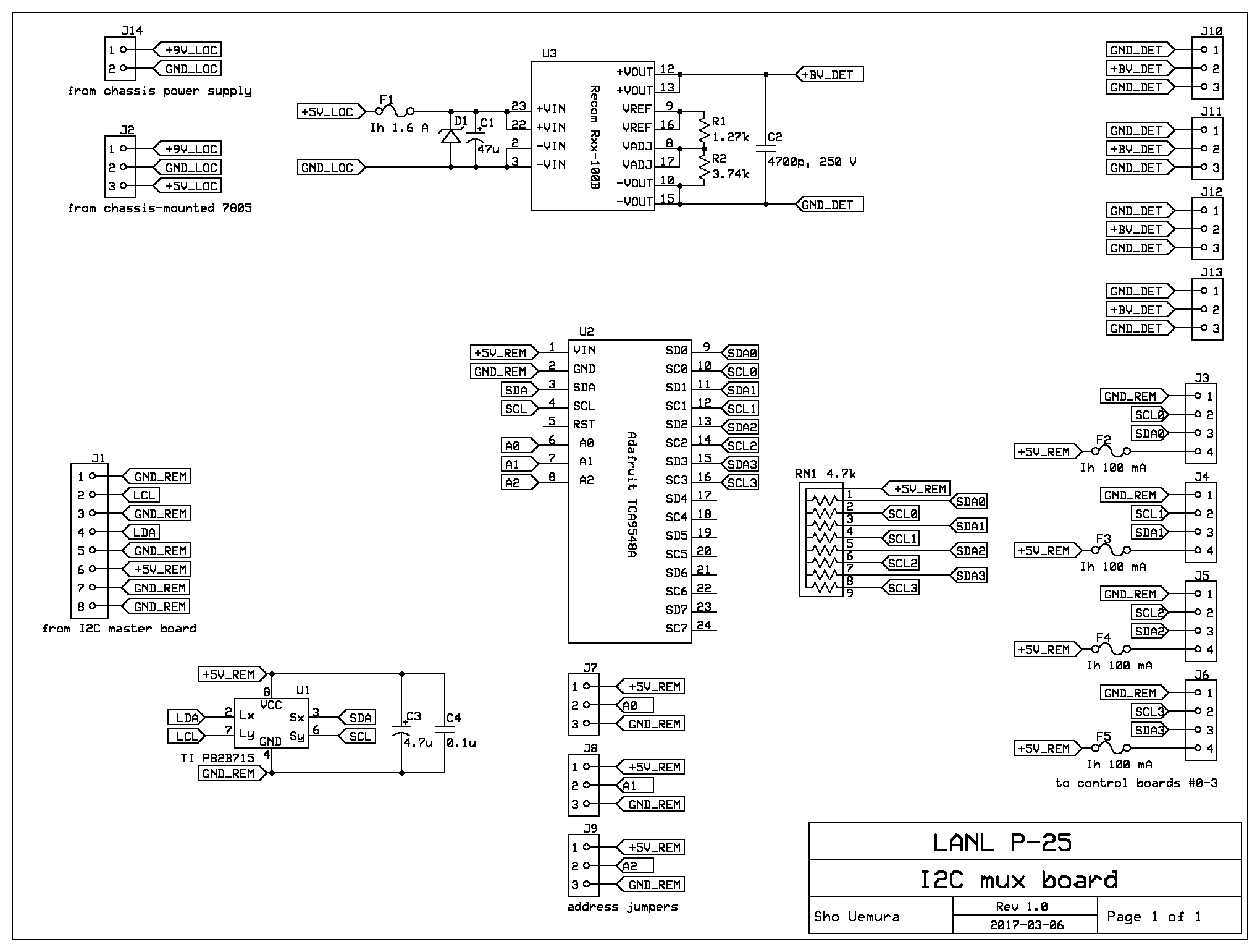
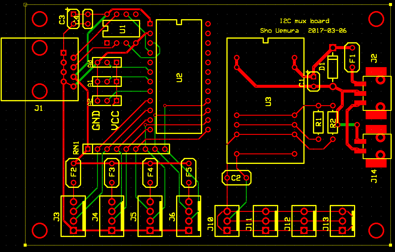
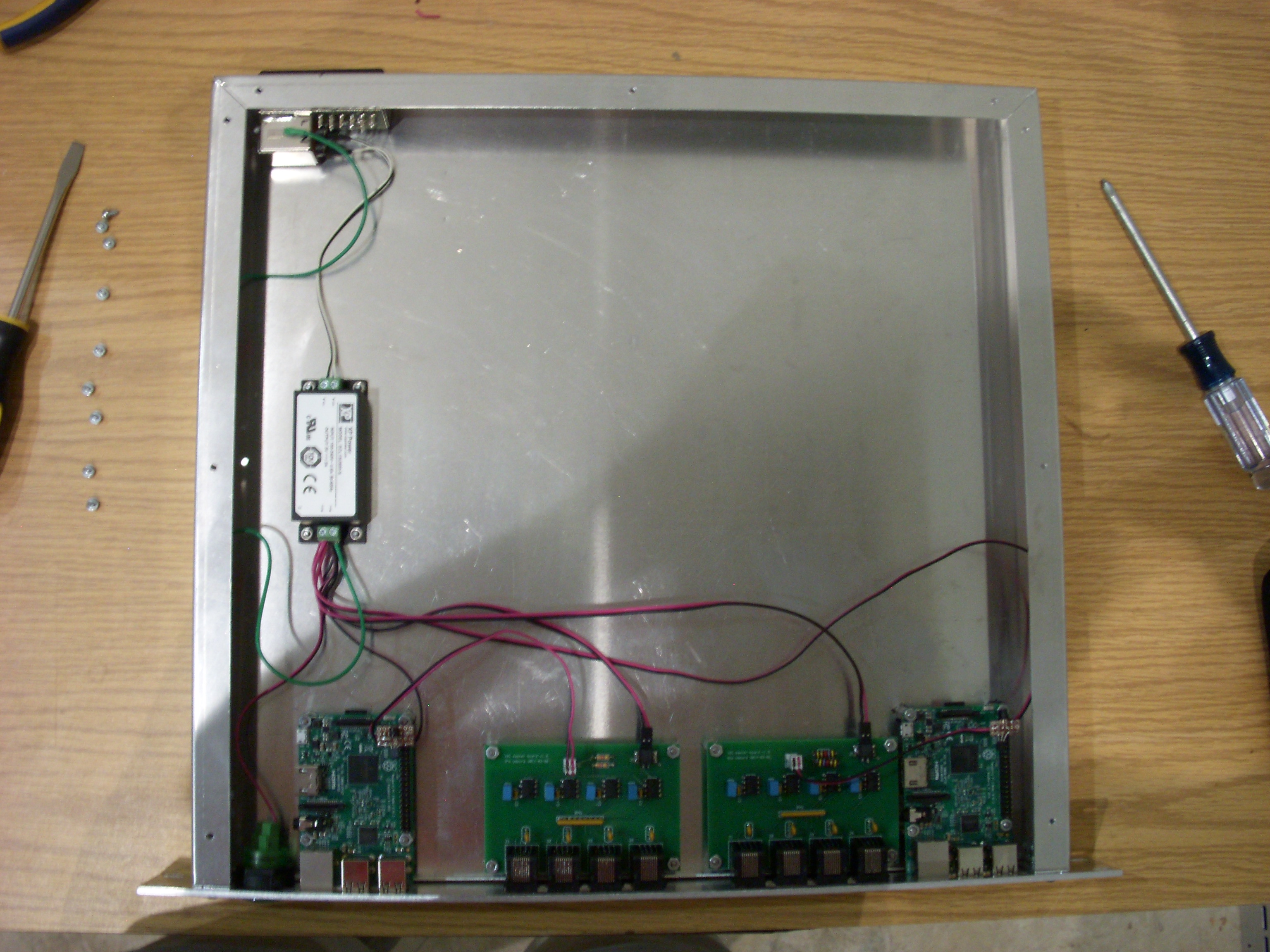
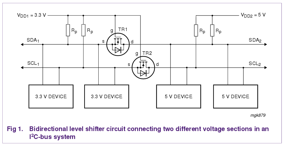
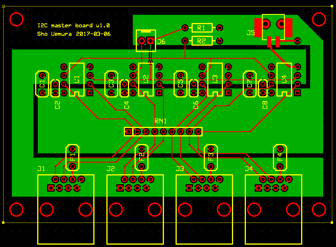
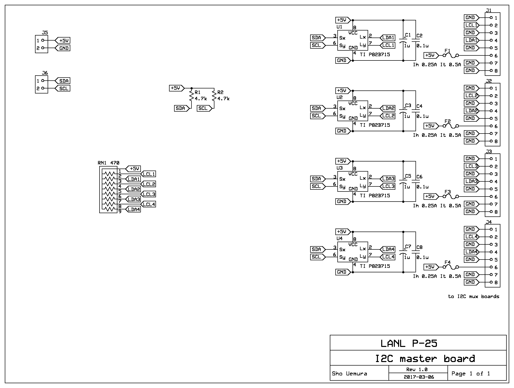
schematic 1

schematic 1

schematic 1

I2C control

All of the voltages are controlled on the control boards, through I2C. We use isolators and I2C extenders to run the I2C lines from all of the control boards to two Raspberry Pis in the master box. Each control board has an isolator chip (Digi-Key 296-34872-1-ND). The isolated side is taken off on a 4-pin connector.

An "I2C mux board" lives in each power chassis. This connects to the 4-pin I2C connectors on each control board. (The mux board also serves as the bulk BV source, but the BV half and I2C half are isolated from each other.) The mux board has an 8-channel mux (Adafruit's breakout board for the TCA9548A), which selects one of the control boards. The mux has an I2C address (0x70-0x77) that is selected by jumpers, so all six muxes can be put on the same I2C bus. An extender chip buffers the common side of the mux so the I2C bus can be put on a long cable. The cable is a standard Ethernet cable with a custom pin assignment, and the extender should be able to drive more than 30 m of cable. The mux board, and the isolated sides of the control board I2C isolators, are powered and grounded by the cable.

The Ethernet cables connect to a master box, which contains a Raspberry Pi and two "I2C master boards." Each master board has four ports; each port has another extender chip and the I2C signals from all of the muxes are brought onto the same I2C bus. The mux and master boards use a 5V I2C bus, and the Pi uses 3.3V, so a small daughterboard sits on the Pi to do the level shifting.


Hodoscope wiring

Each hodoscope box has either 80 channels (station 1 quadrant) or 50 (station 2 quadrant). Each channel comprises an SiPM and a preamp. Low voltage and bias are supplied to the preamp through a 10-pin ribbon cable.

Power and bias are supplied through distribution boards. Each distribution board supplies up to 24 ribbon cables; with one exception, each ribbon cable supplies a single preamp. For the station 1 boxes, the 80 preamps are divided in four equal groups of 20. For the station 2 boxes, the four outermost (furthest from beam) preamps are paired up: two preamps (with gain-matched SiPMs) are connected to the same ribbon cable. Now there are only 48 ribbon cables, so we have two groups.

schematic 1

schematic 1

Preamp, SiPM and pigtail

The active component of the preamp is Mini-Circuits GALI-S66+, with x10 voltage gain. Each preamp has a 10-pin ribbon cable connector for low voltage and bias, and an SMA connector for the amplified signal. On the other side, the preamp has pads for the SiPM. The preamps are mounted to a preamp plate with plastic hardware and spacers, so the preamp ground is isolated and the preamps are only grounded through the ribbon and coax cables.

The SiPM is Hamamatsu S13360-3050CS.

The preamp is connected to the SiPM by a short pigtail of 24 AWG wire (shielded twisted pair, shield grounded to the preamp ground). The SiPM end of the pigtail terminates in a 2-pin connector, so SiPMs can be replaced if necessary.

preamp

Pinout:

  1. Bias
  2. Ground
  3. N.C.
  4. N.C.
  5. RTD bias
  6. N.C. (would be temp/humidity sensor)
  7. RTD output
  8. RTD ground
  9. +6V
  10. Ground

Distribution board

The power ribbons go to a panel which serves as a patch panel and a power distribution board.

This board patches through all the DC voltages for a set of 24 preamps:

  • Bias (+50-60 V, <100 uA)
  • +6V power, common to all preamps (16 mA per preamp, total of 0.4 A)
  • Ground: the preamps have a common ground for bias and power. These grounds are also tied together on the distribution board. The board is meant to be electrically isolated from the frame (no conductive layers extend to the mounting holes).
  • RTDs: the control board exposes two ADC inputs and a regulated +VDD. The distribution board connects these to RTD voltage dividers: one on the first preamp, one using an external RTD (Heraeus 32208711), which we will glue somewhere near the SiPMs.
The board has the same overall dimensions and mounting holes as the coax/fiber patch panel for the 1m boxes. The mounting holes fabbed on the PCB are too small and will need to be drilled out, but the same cutting template can be used.

The ExpressPCB screenshot on the right shows a 100 mil grid.

On the inside (these are drawn in green):

  • 24 10-pin ribbon connectors
  • One 2-pin connector for external RTD

On the outside (these are drawn in red):

  • Four 10-pin ribbon connectors: three for BV (each connector carries 8 voltages), one for RTD connections
  • One big 2-pin connector: +6V
  • One LED to indicate the board is getting +6V, and test points for the BVs
  • Mounting holes to accept 4/40 standoffs: these support a plastic protective cover. The mounting holes have 1.1" vertical separation, 2.7" horizontal.

layout of the distribution board
Electrical diagram for the board. schematic 1

schematic 2

Hodoscope box

The detectors are divided into "hodoscope boxes." DC voltages (preamp power and SiPM bias) enter through "distribution boards." Detector signals exit through "patch panels."

Both sides of the 80-bar preamp plate: left shows the preamps, right shows the pigtails and SiPMs.

preamps pigtails

Internal cabling of the 80-bar hodoscope box.

St1 cabling St1 cabling

Internal cabling of the 50-bar hodoscope box.

St2 cabling

Grounding. Left photo shows the ground wire from the preamp plate to the patch panel, right photo shows the ground wire from the patch panel. This shows a 50-bar box.

preamps preamps


Power supply box

All voltages for the hodoscope boxes are supplied by rack-mounted "power supply boxes." Each power supply box contains a +9V power supply, a custom "mux board," and four custom "control boards." A total of six power supply boxes are used: two power supply boxes for the 50-bar hodoscope boxes and four power supply boxes for the 80-bar hodoscope boxes.

The chassis of the power supply box is grounded through the AC line plug. There are five TO-220 components (a 7805 linear regulator for the mux board, and four power transistors for the control boards) that are bolted to the chassis (using thermal pads for electrical isolation) to dissipate heat.

Block diagram of the power supply box.

schematic 1

Inside and front panel of the power supply box, with the top cover removed.

preamps preamps

Ports and connectors

On the back:

  • AC line plug (with fuse: 250V/2A slow-blow)
  • 8P8C connector for I2C cable to master box

8P8C pinout for buffered I2C:

  1. Ground (paired with LCL)
  2. LCL (buffered SCL)
  3. Ground (paired with power)
  4. LDA (buffered SDA)
  5. Ground (paired with LDA)
  6. Power (+5V)
  7. Ground
  8. Ground

On the front:

  • Green LED, powered from the internal +9V supply
  • Hole (with grommet and strain relief pads) for power cables to hodoscope boxes

The cables to the hodoscopes come out through the hole in the front. Each control board has four 10-pin ribbon cables labeled J1-J4 (corresponding to the connector number on both the control and distribution boards) and one 2-conductor cable labeled LV.

Mux board

The mux board is split in two halves: a I2C section and a bias section. The two halves are electrically isolated.

The I2C section of the mux board is powered and grounded through an 8P8C (Ethernet-like) connector, which also carries buffered I2C signals. This section has two functions: it multiplexes the I2C busses from the four control boards, and it buffers the multiplexed bus so the long Ethernet cable can carry the I2C signals. The multiplexing is done with an 8-channel mux (Adafruit's breakout board for the TCA9548A), which selects one of the control boards. The mux has an I2C address (0x70-0x77) that is selected by jumpers, so all six muxes can be put on the same I2C bus. An extender chip buffers the common side of the mux so the I2C bus can be put on a long cable. The cable is a standard Ethernet cable with a custom pin assignment, and the extender should be able to drive more than 30 m of cable.

The bias section of the mux board takes +9V power from the supply in the power box. The function of this section is to produce a bulk bias voltage (nominally +100V). A switching DC/DC converter creates the bulk bias voltage; since this component requires +5V as input, the +9V supply is lowered to +5V using an off-board 7805 linear regulator.

Electrical diagram of the mux board.

mux board schematic

Layout of the mux board.

mux board layout

Control board

The control board runs on +9V power (from the supply in the power box), plus a bulk BV input at 100 V (from the bias side of the mux board).

Each control board supplies power and bias for one distribution board: 24 independently controlled SiPM bias voltages, and a single preamp supply voltage for 24 preamps.

The nominal bias voltage is in the range from +54 to +56 V, and the nominal current is up to 50 microamps (depending on hit rate and irradiation-dependent dark current). The control board bias circuit is adjustable from 0 to +80 V, and can supply up to 100 microamps.

The nominal preamp voltage is +6V, and the nominal current is 16 mA/preamp.

The components on the control board are controlled via the I2C protocol. The on-board I2C bus is connected to one side of an I2C isolator (ISO1541), and the other side of the isolator is exposed on a 4-pin connector, which is connected to the mux board. The isolator prevents the mux board and master box from tying all the control board grounds together.

Electrical diagram of the control board.

control board schematic

BOM for the control board

I2C addresses:

  • ADC: 0x4b
  • MUX1: 0x4c
  • MUX2: 0x4d
  • MUX3: 0x4e
  • MUX4: 0x4f
  • DAC: 0x55

Internal wiring

Two types of connectors are used for internal wiring.

Low-voltage power is carried on 20 AWG wire with Phoenix Combicon PTSM connectors.

Bulk bias voltage and I2C signals are carried on 24 AWG wire with TE Connectivity MTA-100 connectors.

wire color codes/pinouts:

  • AC power: live black, neutral white, ground green
  • DC power, bulk BV: +6/+9/+100 red, ground black
  • 7805 cable: +9 red, +5 white, ground black
  • NPN transistor cable: emitter white, collector black, base red
  • I2C cable: the red wire is pin 4, pinout is 1=ground, 2=SCL, 3=SDA, 4=5V


Master box

One master box controls all of the power boxes for the hodoscopes.

The master box contains two Raspberry Pis, each of which connects (via a "master board") to up to four power boxes.

schematic 1

preamps

Ports and connectors

On the back:

  • AC line plug (with fuse: 250V/1A slow-blow)

On the front, left to right:

  • Green LED, powered from the internal +5V supply
  • Ethernet port for the first Pi
  • Four 8P8C connectors for I2C connections from the first Pi to power boxes
  • Four 8P8C connectors for I2C connections from the second Pi to power boxes
  • Ethernet port for the second Pi

8P8C pinout for buffered I2C:

  1. Ground (paired with LCL)
  2. LCL (buffered SCL)
  3. Ground (paired with power)
  4. LDA (buffered SDA)
  5. Ground (paired with LDA)
  6. Power (+5V)
  7. Ground
  8. Ground

Raspberry Pi

The master box uses Pi version 3 model B, though any version should work as long as it uses the same pinout.

There is a tiny daughterboard on each Pi. This connects to the top 6 pins of the 40-pin GPIO connector, and has 2-conductor cables going to the +5V power supply and the master board's I2C connector. It supplies +5V power to the Pi, and level-shifts the master board's +5V I2C bus to the Pi's +3.3V I2C port. The only components on this board are two 2N7000 MOSFETs, which are connected as shown in the figure to the right. Note that the Pi has built-in pullup resistors on its I2C pins, as does the master board.

level shifter

Master board

This board contains I2C extenders that allow up to 4 mux boards (and therefore power boxes) to be attached to the Pi's I2C port. All mux boards are put on the same I2C branch (there is no muxing on the master board), so the muxes must have different I2C addresses (the mux boards have jumpers to allow this), and during operation only one mux can be enabled at a time.

The master board was designed such that two master boards could be connected to the same Pi (so the master box would only need one Pi). This turned out not to work because of reflections in the I2C cables connecting the Pi to the master boards.

layout of the master board

schematic 1

Internal wiring

Two types of connectors are used for internal wiring.

Low-voltage power for the master boards is carried on 20 AWG wire with Phoenix Combicon PTSM connectors.

I2C signals are carried on 24 AWG wire with TE Connectivity MTA-100 connectors.

The Raspberry Pis are powered with 24 AWG wire which is soldered directly to the daughterboard.

wire color codes/pinouts:

  • AC power: live black, neutral white, ground green
  • DC power, bulk BV: +6/+9/+100 red, ground black
  • I2C: SCL black, SDA red

Sho Uemura
Last modified: Mon Oct 15 14:48:16 MDT 2018