|
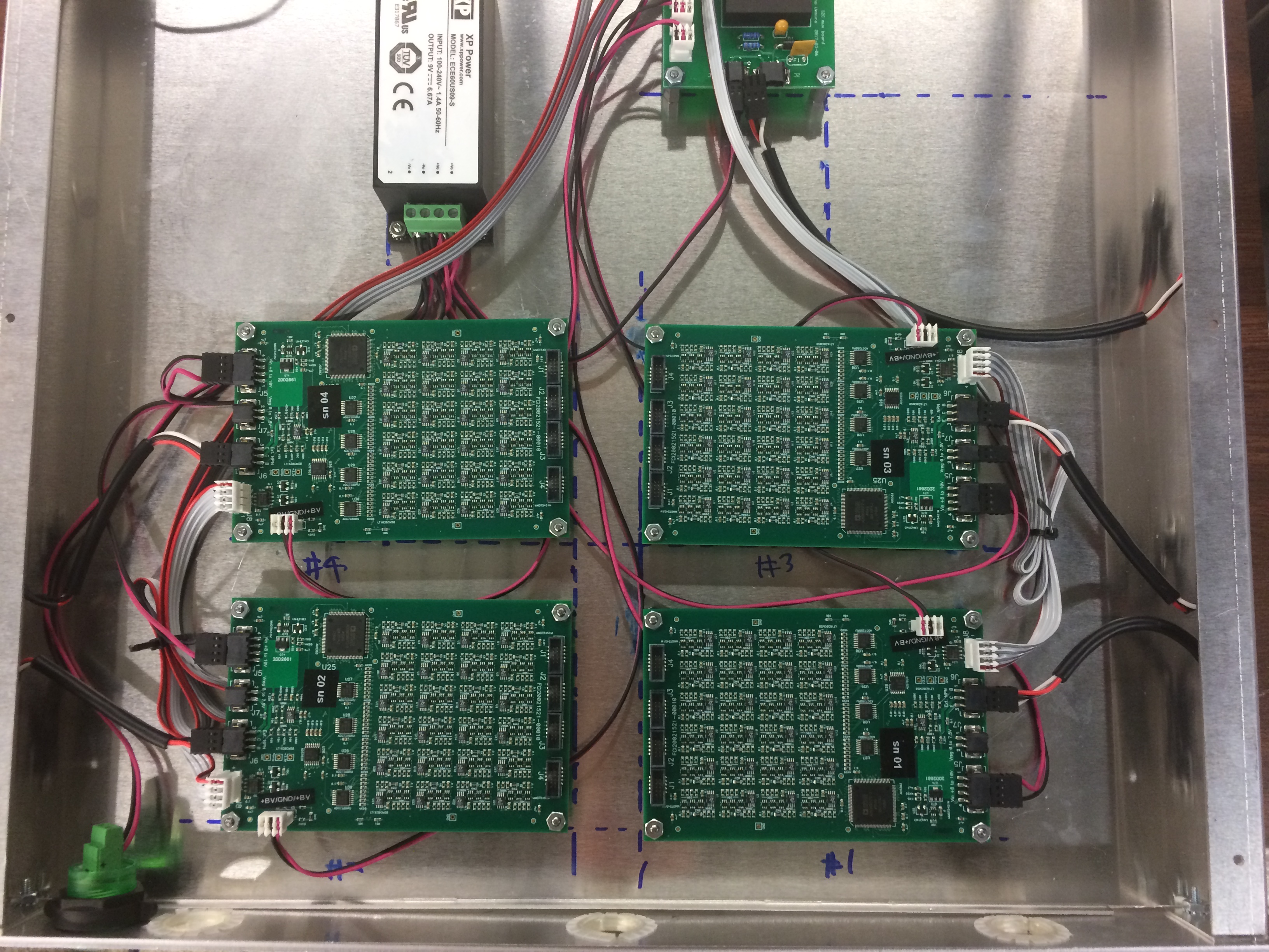
All voltages for the hodoscope boxes are supplied by rack-mounted "power supply boxes." Each power supply box contains a +9V power supply, a custom "mux board," and four custom "control boards." A total of six power supply boxes are used: two power supply boxes for the 50-bar hodoscope boxes and four power supply boxes for the 80-bar hodoscope boxes. The chassis of the power supply box is grounded through the AC line plug. There are five TO-220 components (a 7805 linear regulator for the mux board, and four power transistors for the control boards) that are bolted to the chassis (using thermal pads for electrical isolation) to dissipate heat. |
Block diagram of the power supply box.
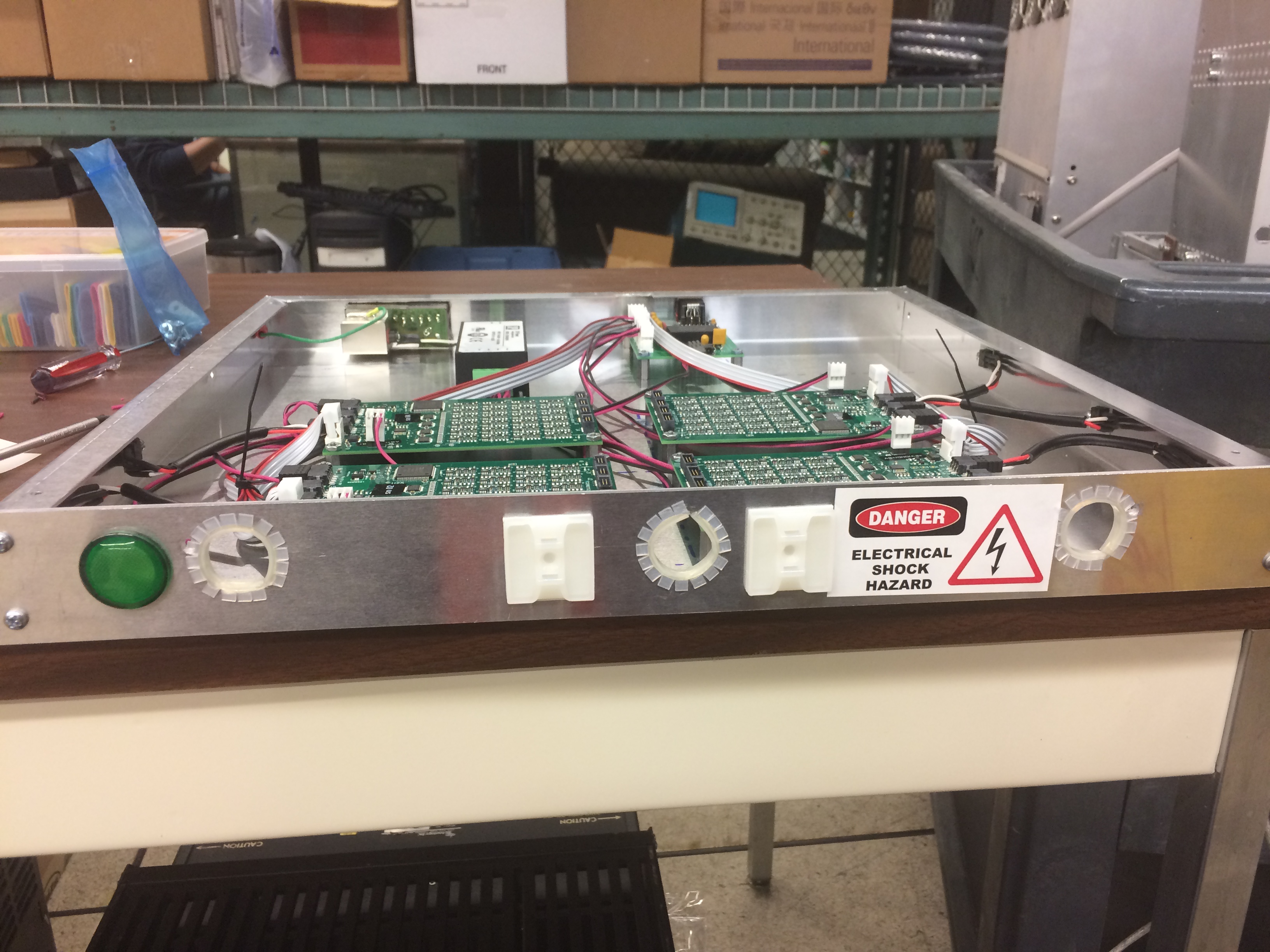
Inside and front panel of the power supply box, with the top cover removed.
|
Ports and connectorsOn the back:
8P8C pinout for buffered I2C:
On the front:
The cables to the hodoscopes come out through the hole in the front. Each control board has four 10-pin ribbon cables labeled J1-J4 (corresponding to the connector number on both the control and distribution boards) and one 2-conductor cable labeled LV. |
|
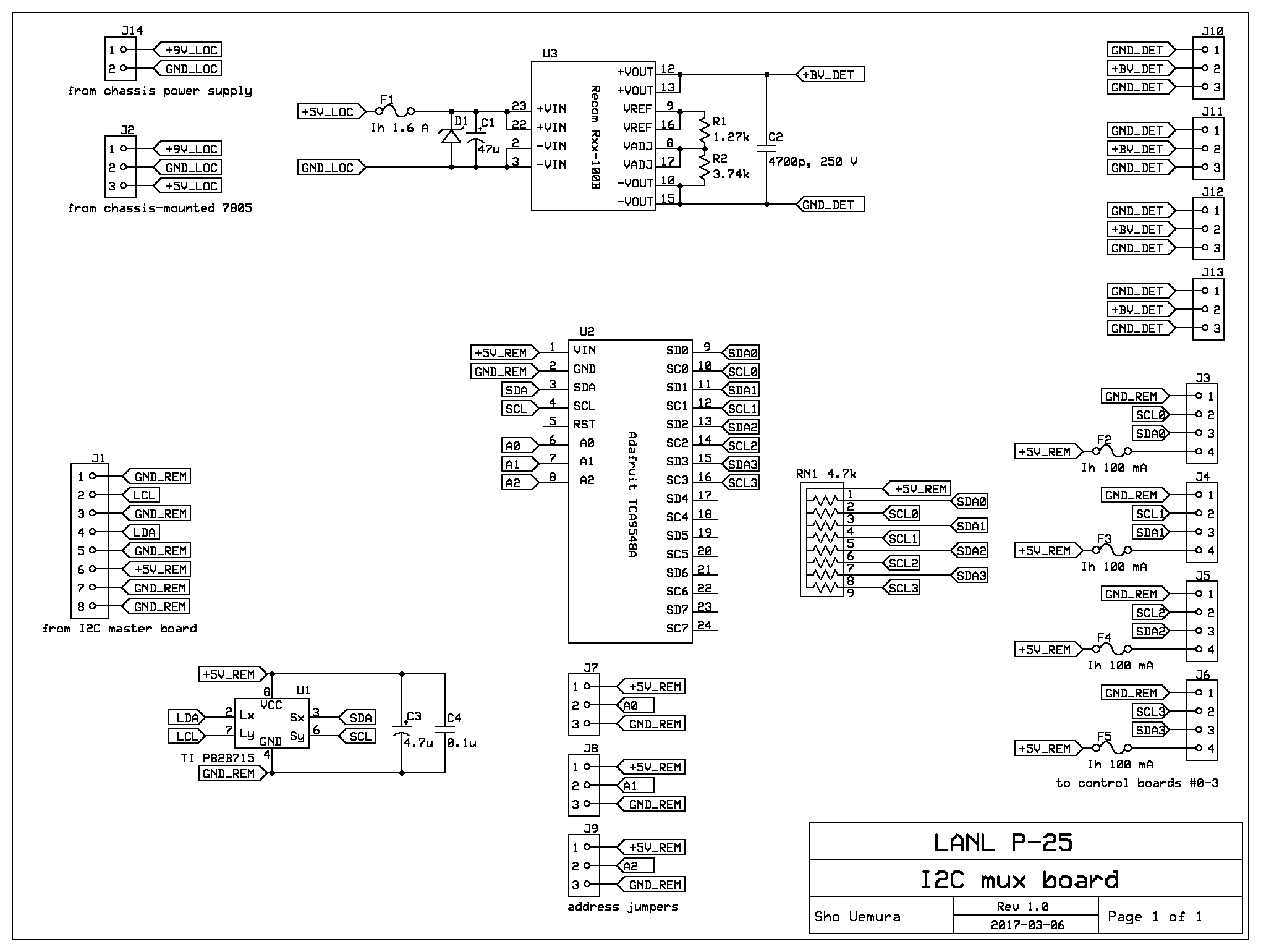
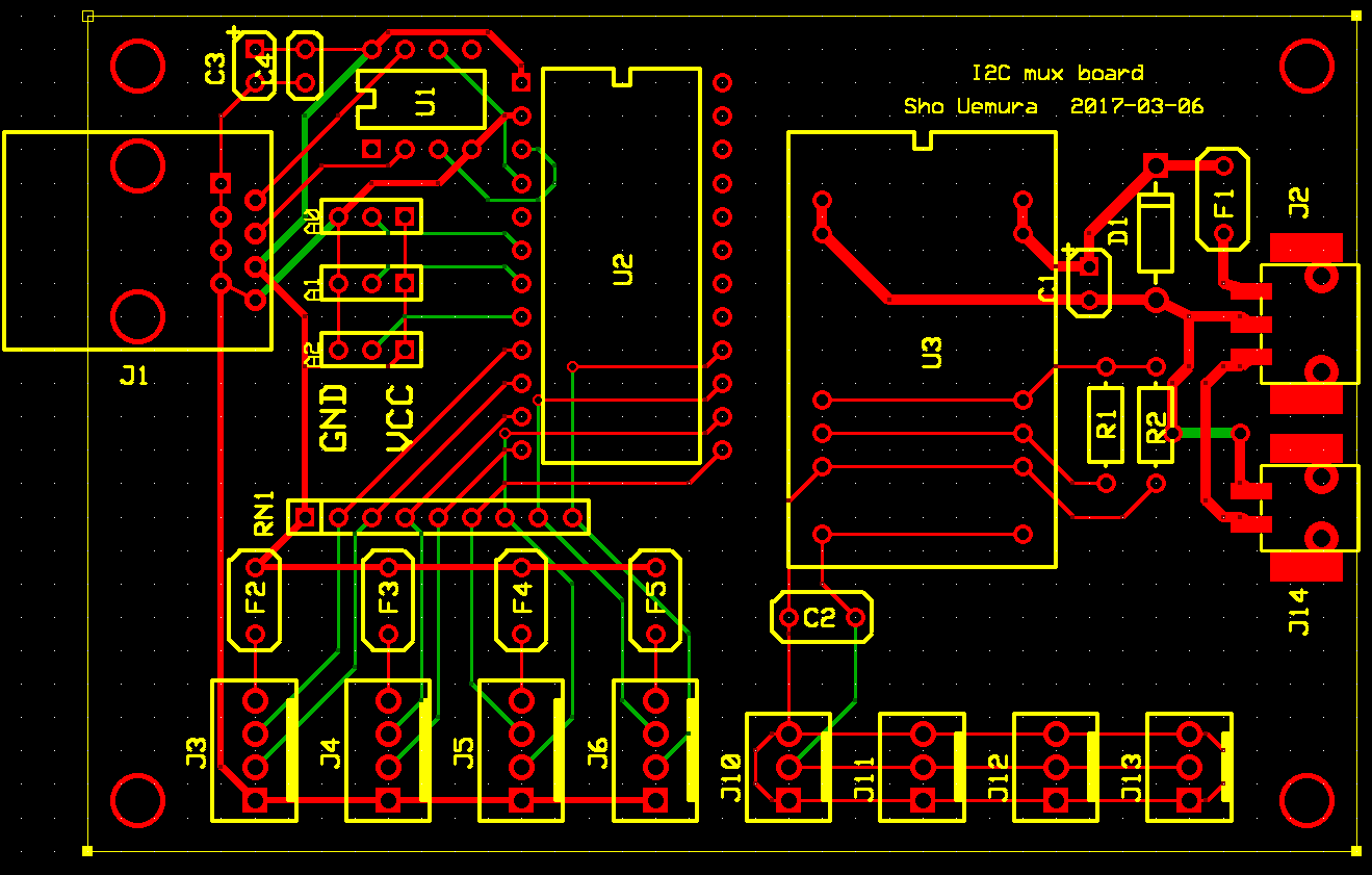
Mux boardThe mux board is split in two halves: a I2C section and a bias section. The two halves are electrically isolated. The I2C section of the mux board is powered and grounded through an 8P8C (Ethernet-like) connector, which also carries buffered I2C signals. This section has two functions: it multiplexes the I2C busses from the four control boards, and it buffers the multiplexed bus so the long Ethernet cable can carry the I2C signals. The multiplexing is done with an 8-channel mux (Adafruit's breakout board for the TCA9548A), which selects one of the control boards. The mux has an I2C address (0x70-0x77) that is selected by jumpers, so all six muxes can be put on the same I2C bus. An extender chip buffers the common side of the mux so the I2C bus can be put on a long cable. The cable is a standard Ethernet cable with a custom pin assignment, and the extender should be able to drive more than 30 m of cable. The bias section of the mux board takes +9V power from the supply in the power box. The function of this section is to produce a bulk bias voltage (nominally +100V). A switching DC/DC converter creates the bulk bias voltage; since this component requires +5V as input, the +9V supply is lowered to +5V using an off-board 7805 linear regulator. |
Electrical diagram of the mux board.
Layout of the mux board.
|
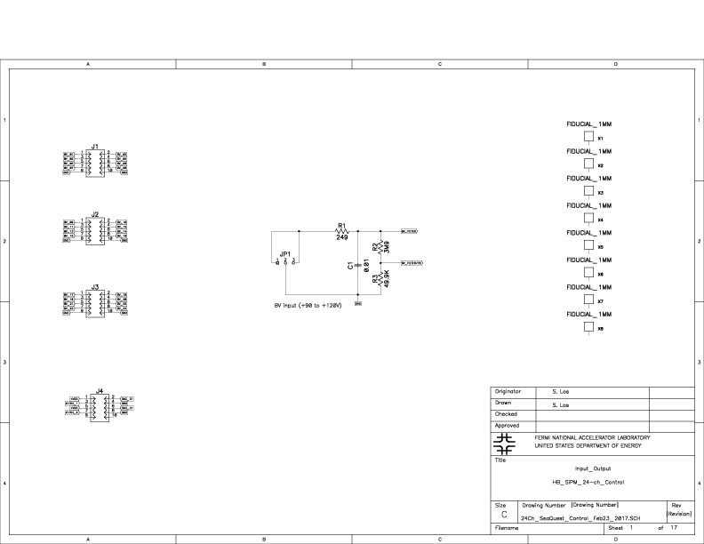
Control boardThe control board runs on +9V power (from the supply in the power box), plus a bulk BV input at 100 V (from the bias side of the mux board). Each control board supplies power and bias for one distribution board: 24 independently controlled SiPM bias voltages, and a single preamp supply voltage for 24 preamps. The nominal bias voltage is in the range from +54 to +56 V, and the nominal current is up to 50 microamps (depending on hit rate and irradiation-dependent dark current). The control board bias circuit is adjustable from 0 to +80 V, and can supply up to 100 microamps. The nominal preamp voltage is +6V, and the nominal current is 16 mA/preamp. The components on the control board are controlled via the I2C protocol. The on-board I2C bus is connected to one side of an I2C isolator (ISO1541), and the other side of the isolator is exposed on a 4-pin connector, which is connected to the mux board. The isolator prevents the mux board and master box from tying all the control board grounds together. |
Electrical diagram of the control board.
I2C addresses:
|
Internal wiringTwo types of connectors are used for internal wiring. Low-voltage power is carried on 20 AWG wire with Phoenix Combicon PTSM connectors. Bulk bias voltage and I2C signals are carried on 24 AWG wire with TE Connectivity MTA-100 connectors. wire color codes/pinouts:
|

Sho Uemura Last modified: Fri May 19 18:50:38 MDT 2017