|
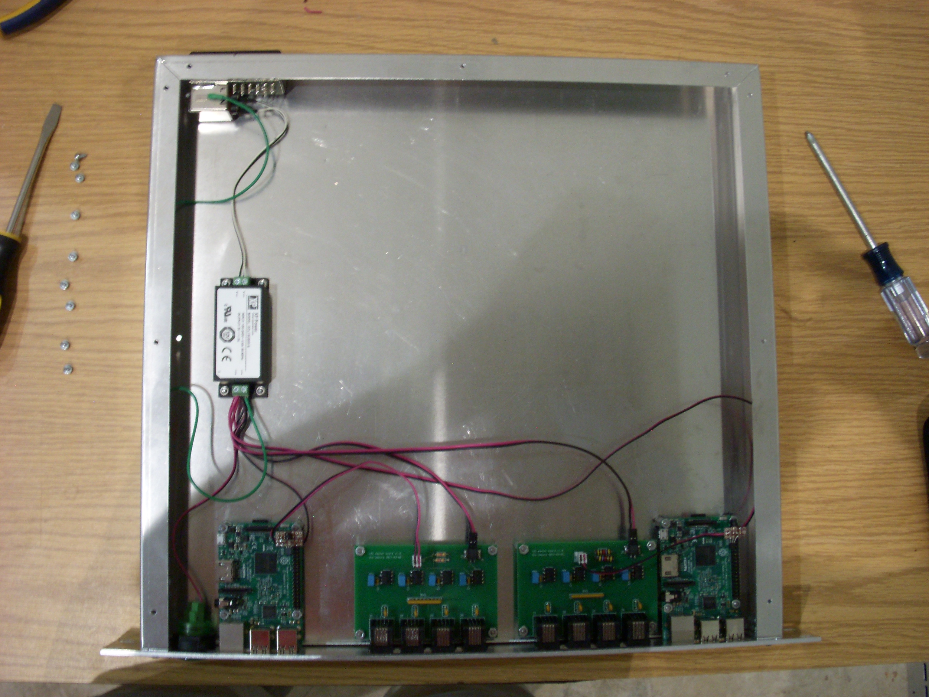
One master box controls all of the power boxes for the hodoscopes. The master box contains two Raspberry Pis, each of which connects (via a "master board") to up to four power boxes. |

|
Ports and connectorsOn the back:
On the front, left to right:
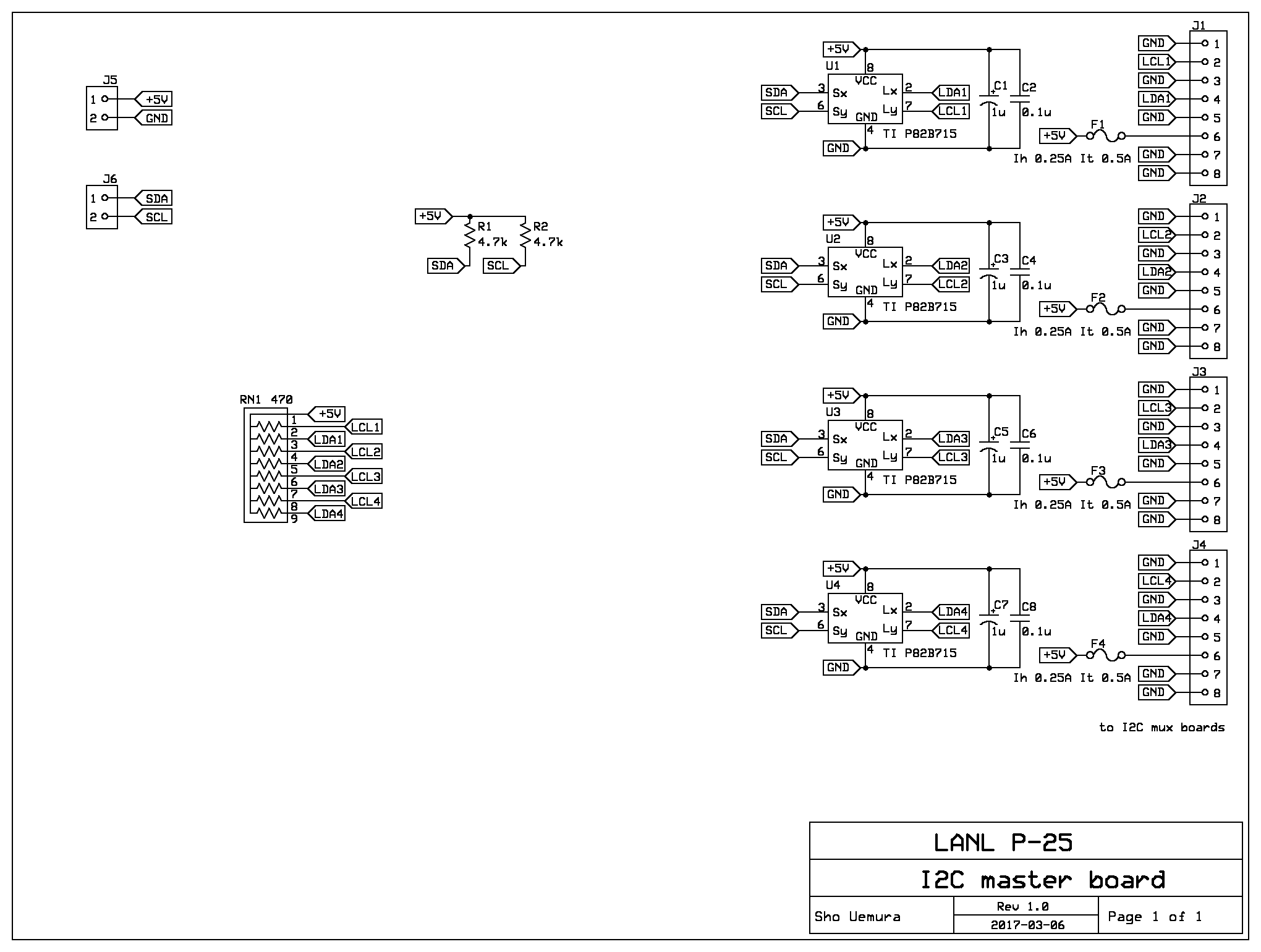
8P8C pinout for buffered I2C:
|
|
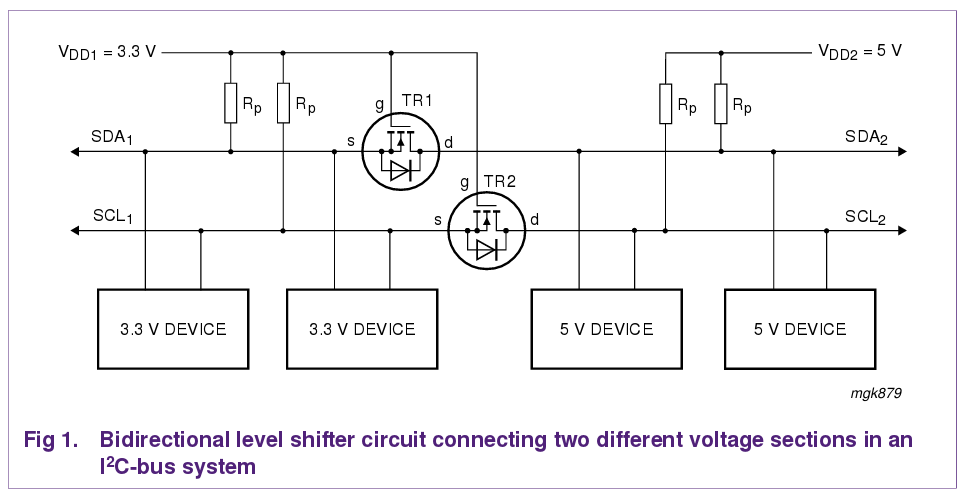
Raspberry PiThe master box uses Pi version 3 model B, though any version should work as long as it uses the same pinout.There is a tiny daughterboard on each Pi. This connects to the top 6 pins of the 40-pin GPIO connector, and has 2-conductor cables going to the +5V power supply and the master board's I2C connector. It supplies +5V power to the Pi, and level-shifts the master board's +5V I2C bus to the Pi's +3.3V I2C port. The only components on this board are two 2N7000 MOSFETs, which are connected as shown in the figure to the right. Note that the Pi has built-in pullup resistors on its I2C pins, as does the master board. |
|
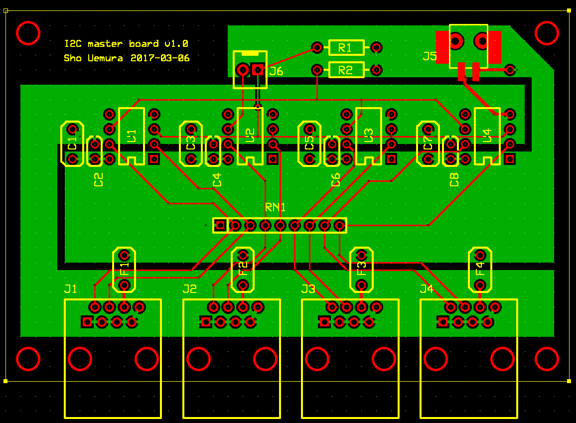
Master boardThis board contains I2C extenders that allow up to 4 mux boards (and therefore power boxes) to be attached to the Pi's I2C port. All mux boards are put on the same I2C branch (there is no muxing on the master board), so the muxes must have different I2C addresses (the mux boards have jumpers to allow this), and during operation only one mux can be enabled at a time.The master board was designed such that two master boards could be connected to the same Pi (so the master box would only need one Pi). This turned out not to work because of reflections in the I2C cables connecting the Pi to the master boards. |
|
Internal wiringTwo types of connectors are used for internal wiring. Low-voltage power for the master boards is carried on 20 AWG wire with Phoenix Combicon PTSM connectors. I2C signals are carried on 24 AWG wire with TE Connectivity MTA-100 connectors. The Raspberry Pis are powered with 24 AWG wire which is soldered directly to the daughterboard. wire color codes/pinouts:
|
Sho Uemura Last modified: Thu Oct 12 19:21:00 MDT 2017