|
Each hodoscope box has either 80 channels (station 1 quadrant) or 50 (station 2 quadrant). Each channel comprises an SiPM and a preamp. Low voltage and bias are supplied to the preamp through a 10-pin ribbon cable. Power and bias are supplied through distribution boards. Each distribution board supplies up to 24 ribbon cables; with one exception, each ribbon cable supplies a single preamp. For the station 1 boxes, the 80 preamps are divided in four equal groups of 20. For the station 2 boxes, the four outermost (furthest from beam) preamps are paired up: two preamps (with gain-matched SiPMs) are connected to the same ribbon cable. Now there are only 48 ribbon cables, so we have two groups.
|
|
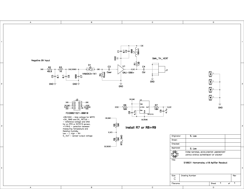
Preamp, SiPM and pigtailThe active component of the preamp is Mini-Circuits GALI-S66+, with x10 voltage gain. Each preamp has a 10-pin ribbon cable connector for low voltage and bias, and an SMA connector for the amplified signal. On the other side, the preamp has pads for the SiPM. The preamps are mounted to a preamp plate with plastic hardware and spacers, so the preamp ground is isolated and the preamps are only grounded through the ribbon and coax cables.The SiPM is Hamamatsu S13360-3050CS. The preamp is connected to the SiPM by a short pigtail of 24 AWG wire (shielded twisted pair, shield grounded to the preamp ground). The SiPM end of the pigtail terminates in a 2-pin connector, so SiPMs can be replaced if necessary. |
Pinout:
|
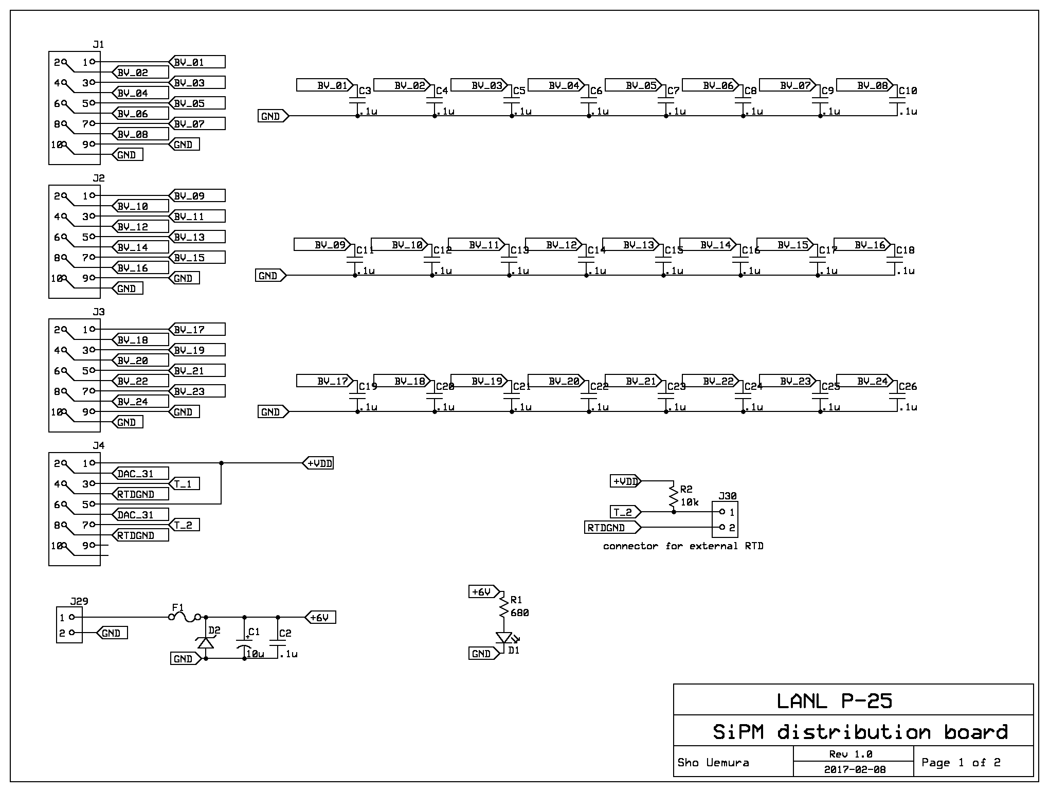
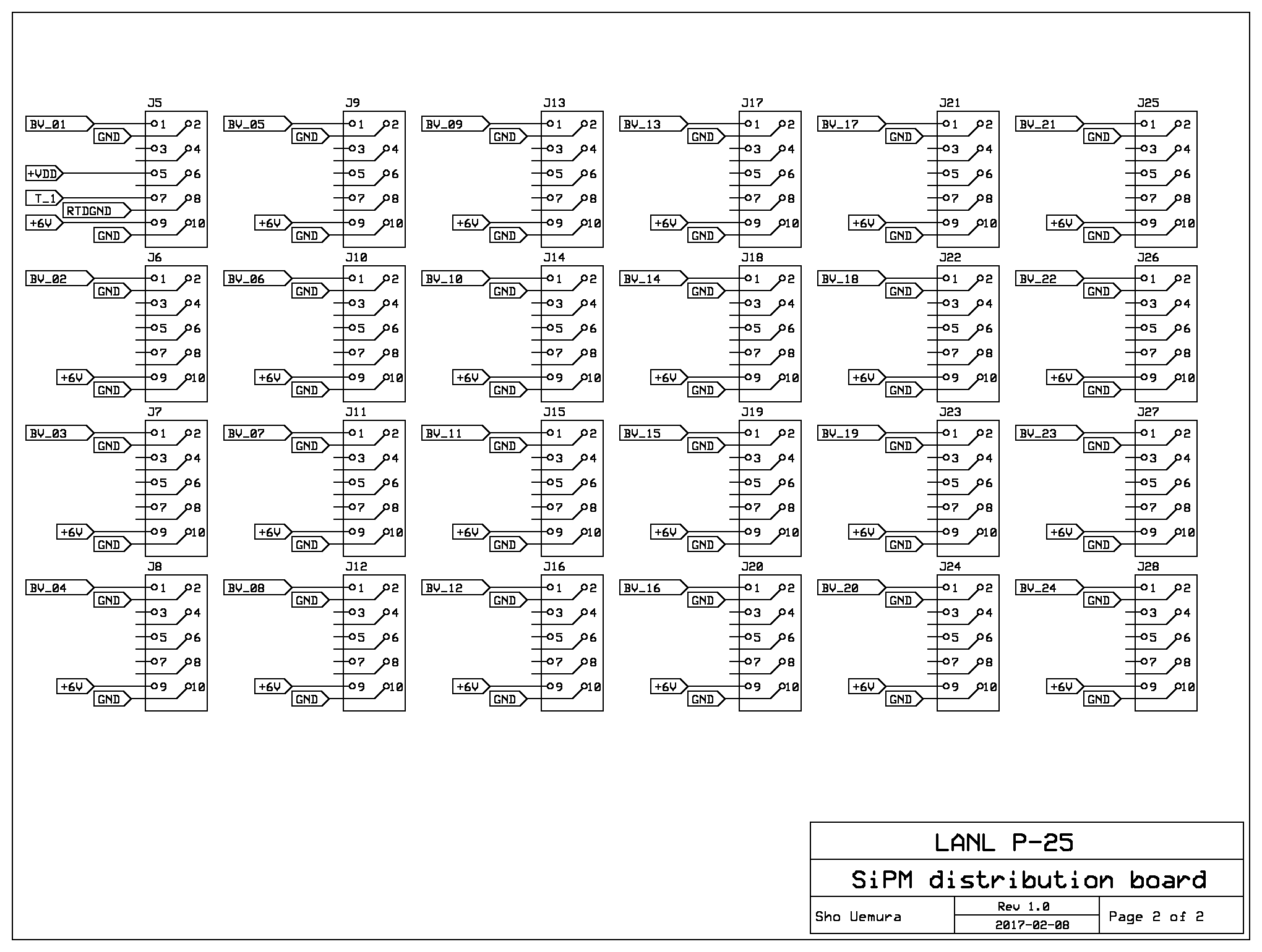
Distribution boardThe power ribbons go to a panel which serves as a patch panel and a power distribution board.This board patches through all the DC voltages for a set of 24 preamps:
|
|
|
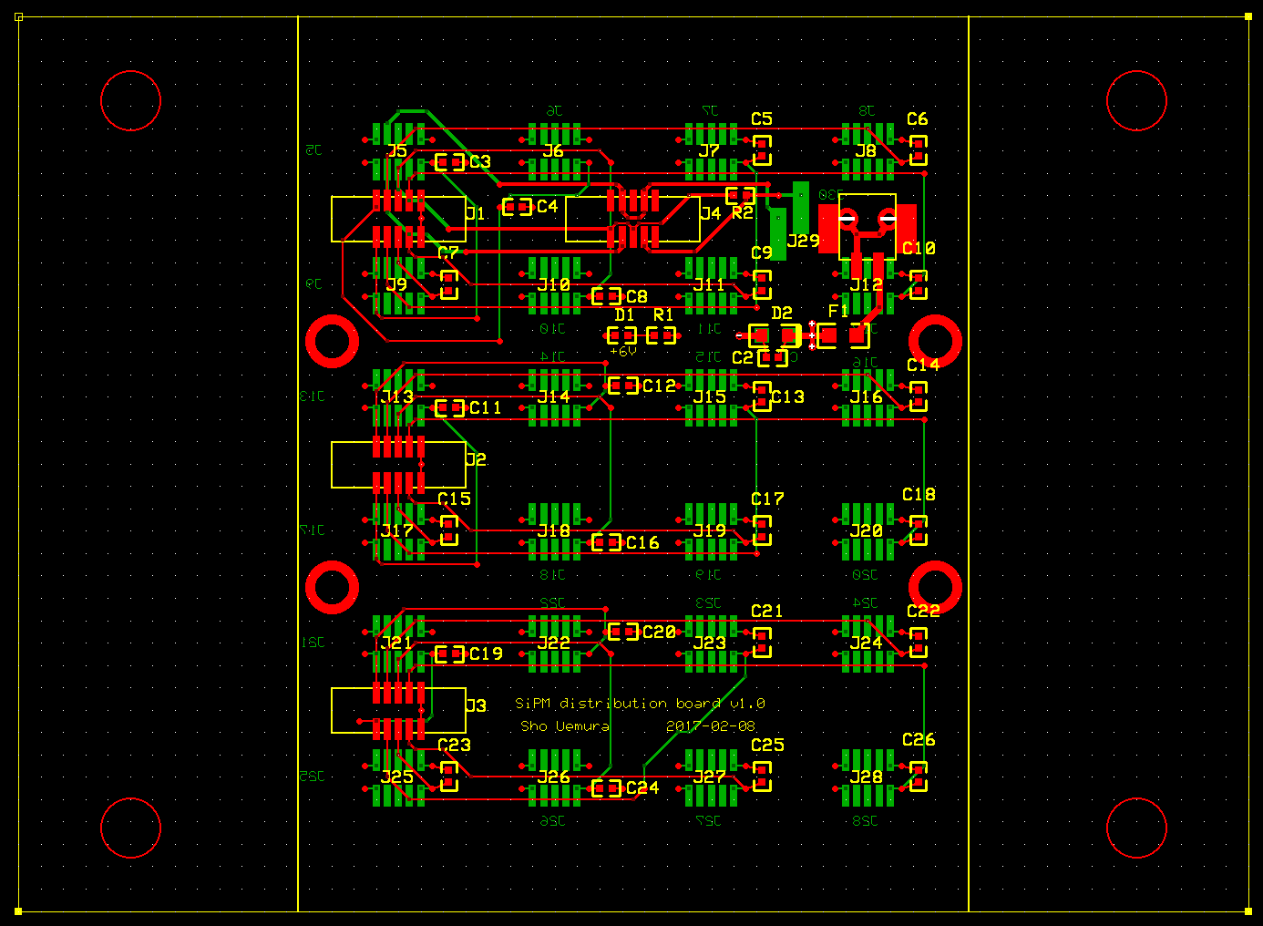
The board has the same overall dimensions and mounting holes as the coax/fiber patch panel for the 1m boxes.
The mounting holes fabbed on the PCB are too small and will need to be drilled out, but the same cutting template can be used.
The ExpressPCB screenshot on the right shows a 100 mil grid. On the inside (these are drawn in green):
On the outside (these are drawn in red):
|
|
| Electrical diagram for the board. |
|
Hodoscope boxThe detectors are divided into "hodoscope boxes." DC voltages (preamp power and SiPM bias) enter through "distribution boards." Detector signals exit through "patch panels." |
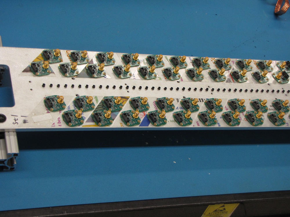
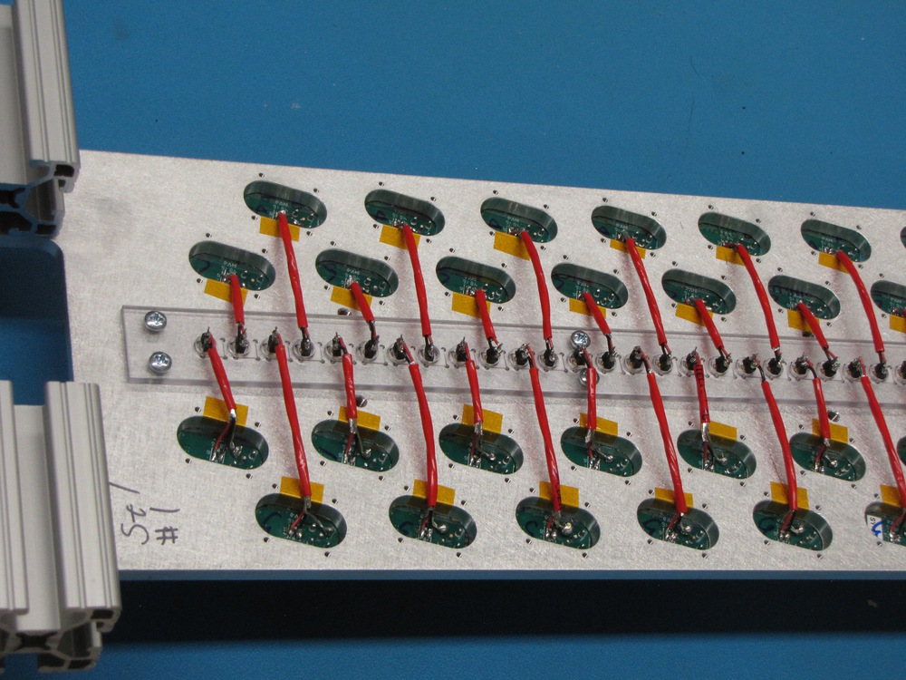
Both sides of the 80-bar preamp plate: left shows the preamps, right shows the pigtails and SiPMs.
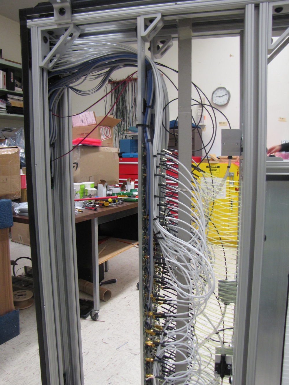
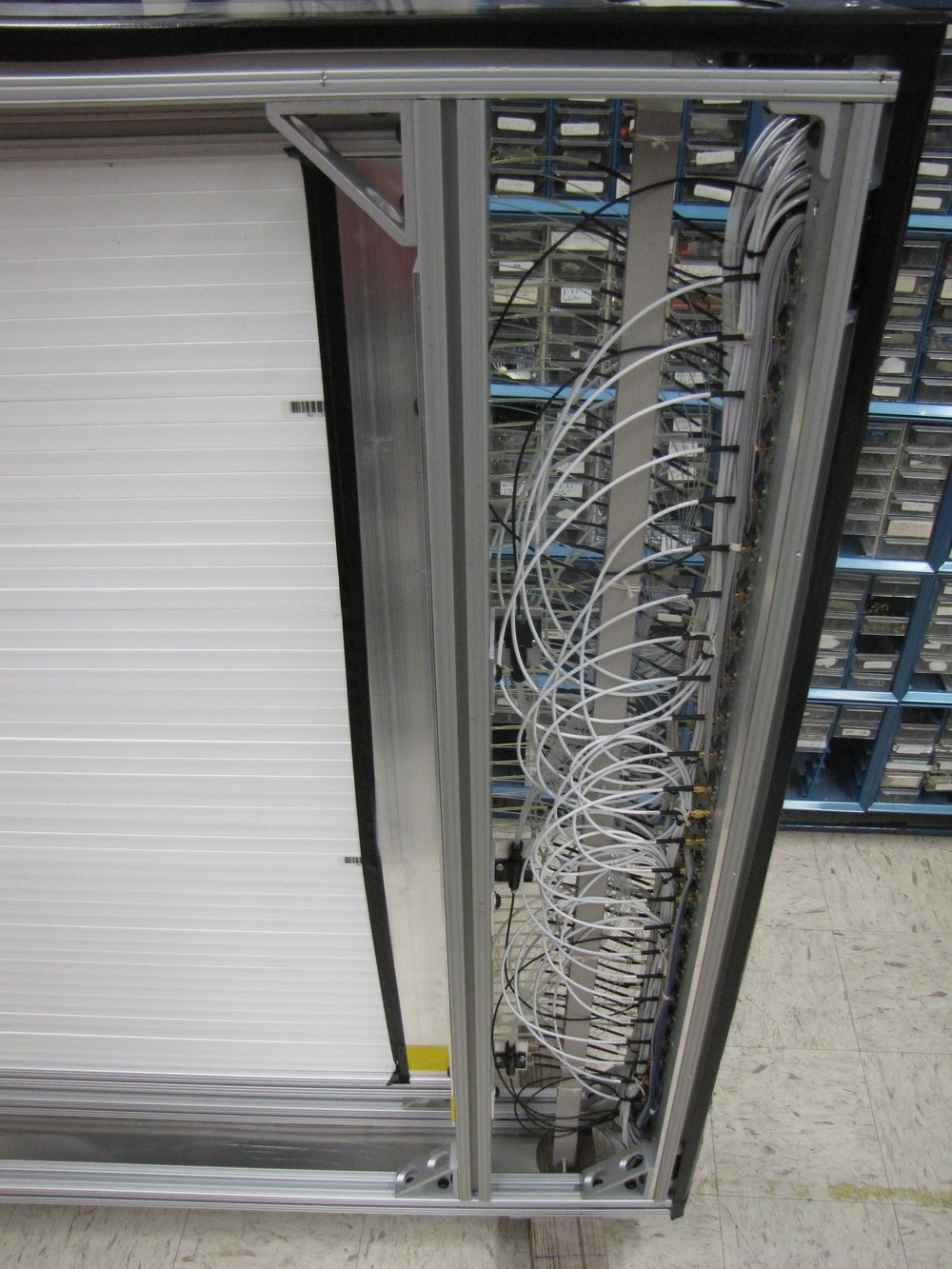
Internal cabling of the 80-bar hodoscope box.
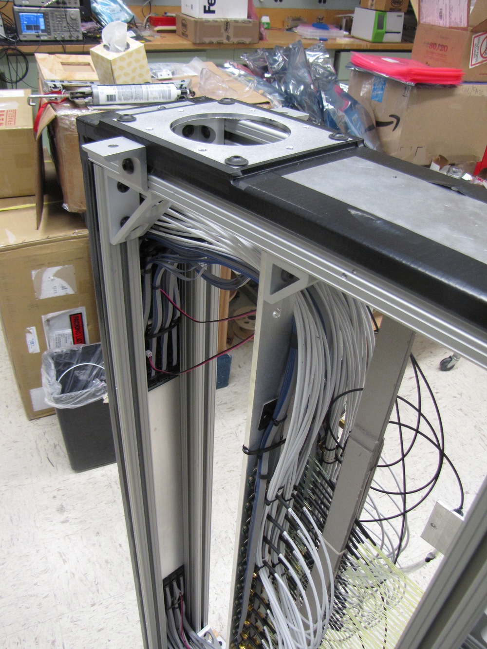
Internal cabling of the 50-bar hodoscope box.
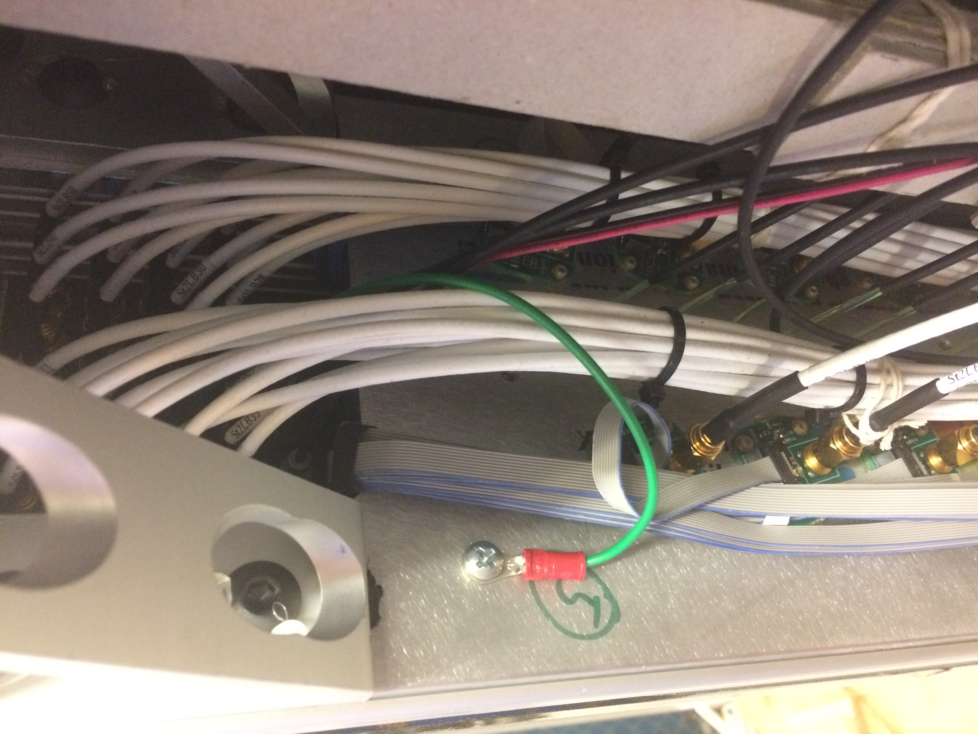
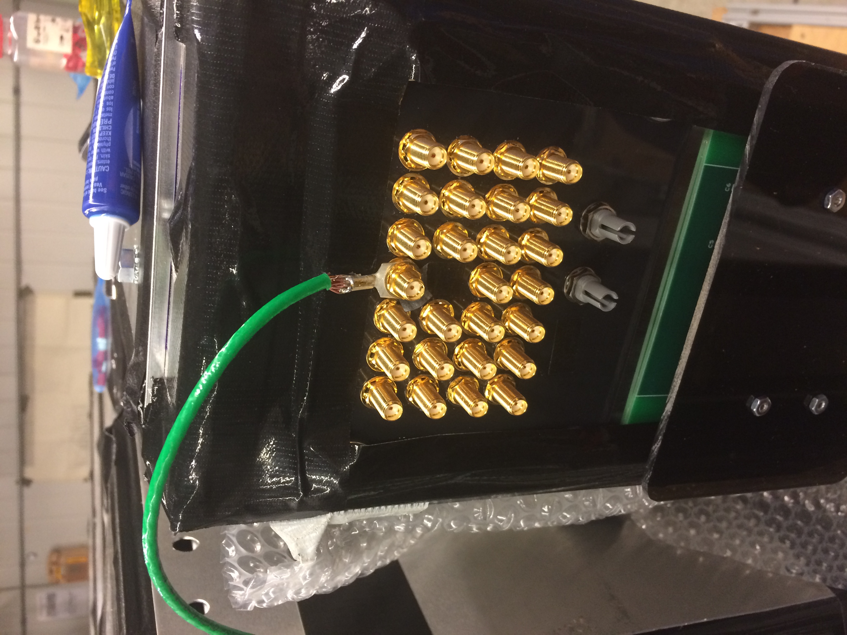
Grounding. Left photo shows the ground wire from the preamp plate to the patch panel, right photo shows the ground wire from the patch panel. This shows a 50-bar box.
|


Sho Uemura Last modified: Wed May 24 12:07:27 MDT 2017