postscript version
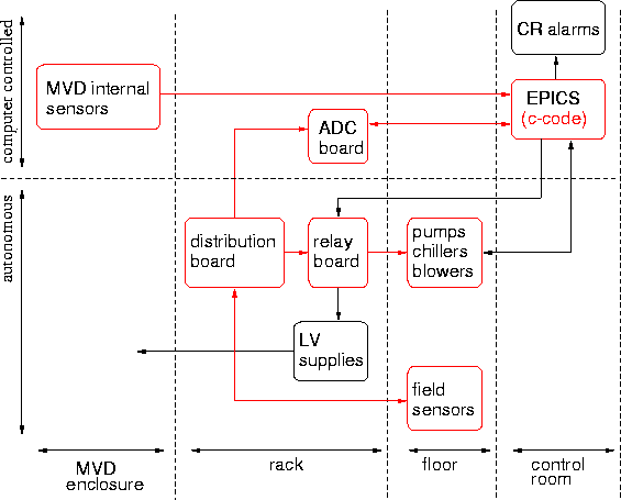
The components and paths in red have already been built and tested. The c-code is a temporary stand-in for EPICS.
Note that we do not use the PLC in this scheme. In the table heading below I added 'or equivalent', which is meant to represent the MVD relay board.
The rack has its own fire and smoke detection, leading to a complete rack shutdown, as can be seen in this diagam of the overall Phenix safety system. The MVD sensors never request a complete rack shutdown, as this would disable all sensors and diagnostics.
The Phenix safety pages can be found here.

| Links to: |
The table below is modeled after this one, requested by Phenix Safety.
The actual values for the temperature and flow trip points will have to be
evaluated once the entire system is constructed and under test. Some known
values are:
item
sensor
control room alarm
L0
PLC controller
or equivalent
L1
trip rack
L2
Phenix crash
L3
what is
tripped
comments
a) MVD East half air and water:
1
T1
East half cooling air supply temperature
T1>xxx°C
2/3 decision
T1 > xx°C
T2 > xx°C
T3 > xx°C
no
no
MVD East half
Majority decision made by the relay board.
Shutdown decision cuts blower, chiller
and LV supplies for the East half.
2
T2
East half plenum air return temperature
T2>xxx°C
3
T3
East half enclosure air return temperature
T3>xxx°C
4
F1
East half cooling air supply flow
F1<xxx l/min
2/3 decision
F1<xxx l/min
F2<xxx l/min
F3<xxx l/min
no
no
MVD East half
Majority decision made by the relay board.
Shutdown decision cuts blower, chiller
and LV supplies for the East half.
5
F2
East half plenum air return flow
F2<xxx l/min
6
F3
East half enclosure air return flow
F3<xxx l/min
7
H1
East half return air humidity
Relative Humidity > xx% or < xx%
no
no
no
8
T4
East half liquid supply temperature
T4>xx°C
2/2 decision
T4 > xx°C
T5 > xx°C
no
no
MVD East half
Majority decision made by the relay board.
Shutdown decision cuts liquid pump
and LV supplies for the East half.
9
T5
East half liquid return temperature
T5>xx°C
10
F4
East half liquid supply flow indicator
F4<xx l/min
2/2 decision
F4<xxx l/min
F5<xxx l/min
no
no
MVD East half
Majority decision made by the relay board.
Shutdown decision cuts liquid pump
and LV supplies for the East half.
11
F5
East half liquid return flow indicator
F5<xx l/min
b) MVD West half air and water:
12
T6
West half cooling air supply temperature
T6>xxx°C
2/3 decision
T6 > xx°C
T7 > xx°C
T8 > xx°C
no
no
MVD West half
Majority decision made by the relay board.
Shutdown decision cuts blower, chillers
and LV supplies for the West half.
13
T7
West half plenum air return temperature
T7>xxx°C
14
T8
West half enclosure air return temperature
T8>xxx°C
15
F6
West half cooling air supply flow
F6<xxx l/min
2/3 decision
F6<xxx l/min
F7<xxx l/min
F8<xxx l/min
no
no
MVD West half
Majority decision made by the relay board.
Shutdown decision cuts blower, chillers
and LV supplies for the West half.
16
F7
West half plenum air return flow
F7<xxx l/min
17
F8
West half enclosure air return flow
F8<xxx l/min
18
H2
West half return air humidity
Relative Humidity > xx% or < xx%
no
no
no
19
T9
West half liquid supply temperature
T9>xx°C
2/2 decision
T9 >xxx°C
T10>xxx°C
no
no
MVD West half
Majority decision made by the relay board.
Shutdown decision cuts liquid pump
and LV supplies for the West half.
20
T10
West half liquid return temperature
T10>xx°C
21
F9
West half liquid flow indicator
F9<xx l/min
2/2 decision
F9<xxx l/min no
no
MVD West half
Majority decision made by the relay board.
Shutdown decision cuts liquid pump
and LV supplies for the West half.
22
F10
West half liquid flow indicator
F10<xxx l/min
c) MVD Motherboard temperatures
23
NW motherboard temperature sensor
T>xx°C
T>xx°C
no
no
NW motherboard power
24
NE motherboard temperature sensor
T>xx°C
T>xx°C
no
no
6,18...or 36 MCM's
and/or NE motherboard
25
SW motherboard temperature sensor
T>xx°C
T>xx°C
no
no
6,18...or 36 MCM's
and/or SW motherboard
26
SE motherboard temperature sensor
T>xx°C
T>xx°C
no
no
6,18...or 36 MCM's
and/or SE motherboard
d) MVD Motherboard voltages
27
NW motherboard voltage monitor
V<xx V
V<xx V
no
no
NW motherboard power
28
NE motherboard voltage monitor
V<xx V
V<xx V
no
no
6,18...or 36 MCM's
and/or NE motherboard
29
SW motherboard voltage monitor
V<xx V
V<xx V
no
no
6,18...or 36 MCM's
and/or SW motherboard
30
SE motherboard voltage monitor
V<xx V
V<xx V
no
no
6,18...or 36 MCM's
and/or SE motherboard
e) MCM temperatures
31
individual MCM temperature sensor
T>xx°C
T>xx°C
no
no
6 MCM's
Power is shared by 6 MCM's.
f) radiation monitors
32
8 Si radiation monitors
rate>xxx/sec
rate>xxx/sec
yes?
no?
Selected Phenix systems (HV, LV...)
Only take down systems that can be damaged by radiation in a power-up
state.
Sources: