MVD Custom ADC module
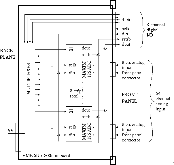
VME board layout. Below is a sketch of the custom ADC readout board. Essentially this is a copy of the hardware on the MVD motherboard. We will use this board to read out the sensors (temperature, flow, humidity) around the MVD cooling system.
The top 8 lines on the front panel are driven by a digital I/O board in the VME crate (such as one of these). This board in turn is driven by a C-routine (using existing examples from TC) running in the MVME162, [which in turn is activated as an EPICS subroutine record.]
As a general-purpose Phenix board, we can design it for the maximum of 128
single-ended or 64 differential analog inputs. For the MVD, we use 64
differential.

Postscript version
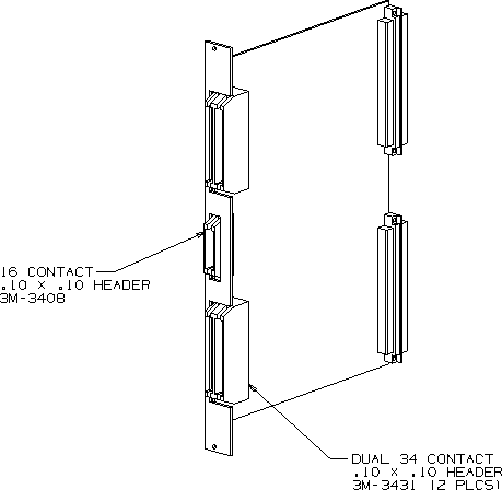
 Postscript version | On the final board the 16-pin connector is at the top and the two condo connectors are below it. On the backplane the bottom connector is unused, and is not installed on one of the 2 boards that were built. |
Links:Maxim,
Parts
                part              value              have     need
  -----------------------------------------------------------------
  D1                              green diode        many BNL  0
  D2                              red diode          many BNL  0
  R1, R7                          150                 2        0
  R2                              24K                 1        0
  R3,4,5,6                        24                  4        0
  C01,02,03,04,06,08,09,10,12,13,
   14,16,17,18,20,21,22,24,25,26,
   28,29,30,32,33,34,36,37,38,40,
   41,42,44,45,46,48,49,50,52,53,
   54,56,57,58,60,61,62,64,65,66,
   68,69                          ?? (DECOUPLING)     -       52
  C5                              22 uF               1        0
  C07,11,15,19,23,27,31,35,39,43,
   47,51,55,59,63,67              4.7 uF              16       0
  U1,2                            74ACT138PC          1        0
  U3                              DM74123N            1        0
  U4                              74ACT244PC          1        0
  U05,06,07,08,09,10,11,12,13,14,
   15,16,17,18,19,20              MAX186_CPP          -       16
                   17             20-pin socket       -       17
                    3             16-pin socket       3        0
  P2                              VME backplane      many      0
  P3                              16-PIN RH HEADER   some BNL  0
  P4,5                            2X34-PIN CONDO      0        2
                                  FRONT PANEL         -        -

             pulldown resistor    13M (?)             0       64
             pulldown cap         .22uF               ?       64
  ------------------------------------------------------------------
Modifications:
-
On the board, the backplane connectors P1 and P2 were reversed. All we use
from the backplane is +5V and ground, and these are picked off the top
connector P1 with fat wires and brought down to where they connect to the
board by the P2 connector.
-
The 64 input lines were floating, and they need to be terminated to ground. A
little daughter board on the back pulls the input to ground via 2 (4, 13)Mohm
resistors, plus .22 uF caps to ground:
First the connector pins, where they stick out through the back of the
board:

                   top of board

                   four columns
                   of 17 pins:

 b                  1  2  3  4       f
 a                  2                r
 c                  3                o
 k                  4                n
                    5                t
 o                  6
 f                  7
                    8
 b                  9
 o                 10
 a                 11
 r                 12
 d                 13
                   14
                   15
                   16
                   17

                 bottom of board


    Every pin except the top row in columns 1 and 3 has a similar
 looking arangement:


 Cap   2Mohm resistor?      4Mohm resistor?    Cap --> Ground on this side
 ^ ^   ^             ^      ^            ^     ^
 | |___|             |      |            |_____|
 g     |             _______|            pin from column 3 attached here
 r     |                    |
 o     |                    ground (I think) here
 u     |
 n     pin from column 1 attached here
 d

 Some of the conections are on the back of a small breadboard so
 it is confusing. There are also three ground (I assume) wires
 from the breadboard to points on the back of the ADC board.
 I do not understand the values of the resistors. I give you
 what I measure across them. However, by their colors, th 2 and 4
 Mohm resistors should be the same (or maybe I can't tell the colors).
 yellow - gold? - blue - orange - brown.

 The caps say:
 224
 35K
 548
 on them. In each case, the brown band on the cap is towards the
 middle of the arrangement above.

 Is that enough?
 John (Feb 16 2000)
back