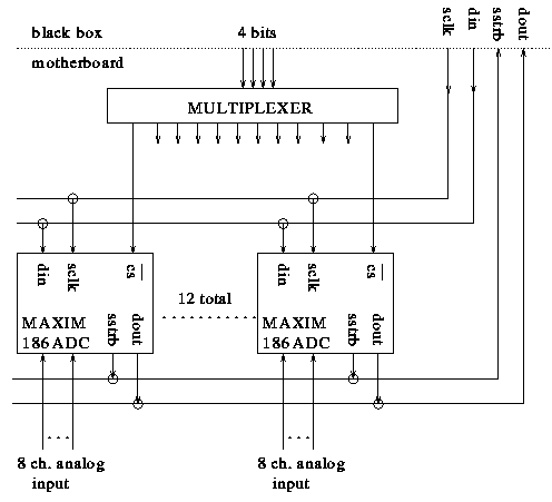
To read out the numerous voltages on the motherboard (of which there are 4), the following scheme is proposed:
The MAXIM Max186 is an 8-channel, serial, 12-bit ADC. We will have 12 on each
motherboard. In order for a particular chip to become active, its CS-bar line
needs to be pulled low. Using 4 bits and a multiplexer, one chip at a time is
thus activated.
[We will not use the 'shutdown feature' of this chip, but tie
this line high in order to use the internal voltage reference of the 186].
Next, in order to choose which of the 8 analog channels gets digitized, and to set up other parameters, a string of 8 bits needs to be clocked into the chip. This is done using the DIN and SCLK lines. After the data is clocked in, the clock keeps on running, in order to clock the data out. The data appears on DOUT one click after SSTRB goes high.
After the 12 bits are received, the next byte into DIN will select the next analog channel on this chip, and so on. Once all 8 channels are done, the bits into the multiplexer will select the next Max186 chip and the process repeats.

2) Can we have EPICS fire up this serial program?
Back to the MVD ancillary systems