MVD ancillary - the relay board
The relay board is housed in a VME crate, but no VME protocols are used. Only power and ground are taken from the backplane connectors.
A 2/3 vote of T1,T2,T3, and/or a 2/3 vote of F1,F2,F3 will bring the system down. Also if both T4,T5 and/or both F4,F5 say flow is bad, this will bring down the system.
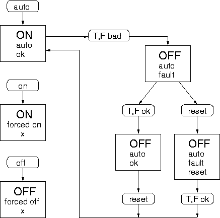
There is a latching circuit such that if the conditions come back to normal, the system stays off until a computer reset command has been given saying that all is OK. This prevents the power from cycling over and over autonomously.
In addition, computer overrides are available to turn the chillers, pump and fan on.
The entire circuit is copied on the lower half of the board to service the West half.
Dec 2000: I added the AND gate just beyond the latch. This prevents the circuits from going on upon reset, if the sensors still report a fault. Also added the readback line, to check on the output of the sensor decision tree.
Info about the actual PC board (chips, layout etc) is here.

Front panel connector
pin assignments on the next page.
 This is a partial state diagram that shows the operation of the board in the
AUTO mode. Square boxes are states, rounded boxes are events or operations. In
AUTO mode, the system goes down if the sensors decide here is trouble. In
order for the system to come back up, two things have to happen: the sensors
have so agree that the system is OK, and someone has to issue the RESET
command. These two things can happen in either order.
Of course, there are always the ON and OFF commands, which force the system on
or off, regardless of the opinion of the sensors.
ps