M54/74HC20 dual 4-input NAND gate (9 pages pdf)
MC54/74HC74A Dual D flip-flop with set and reset (7 pages pdf)
SN54/74HC02 Quad 2-input positive NOR gates (4 pages ps)
SN54/74HC04 Hex inverters (4 pages psps)
SN54/74HC08 Quad 2-input positive AND gates (4 pages ps)
SN54/74HC32 Quad 2-input positive OR gates (4 pages ps)
  shopping list
 +-----------------------------------------------------+
 |            32    32     02            32   32   02  |
 |            20                         20            |
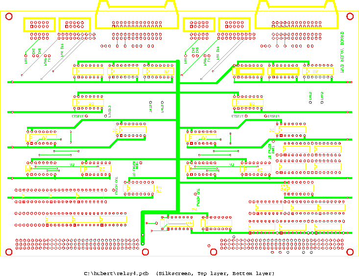
 |                  32                         32      |  chips on the board
 |     02                          02                  |
 |     32        02                32      02          |
 |                      04                       04    |
 |                              74   08                |
 +-----------------------------------------------------+

                        2-board
              detail       total      have
 ----------------------------------------------
   '32'      TI SN74HC32N    16         9
   '02'      TI SN74HC02N    12         0
   '20'      ST M74HC20B1     4         2
   '04'         SN74HC04N     4         2
   '74'      MO MC74HCT74AN   2         1
   '08'      TI SN74HC08N     2         1
 connector   10-pin mini      8         8
 connector   26-pin           4         ? part of old order?
 connector   VME backplane    4         4
 caps                        40         
 jumpers                     56        56  need some more
 boards                       2         2
 ----------------------------------------------


  PIN ASSIGNMENTS

pin function
1 T1
3 T2
5 T3
7 F1
9 F2
11 F3
13 T4
15 T5
17 F4
19 F5
21 unused
23 unused
25 unused
This is the 26-pin connector which takes the sensor signals from the sensor distribution board. Even pins are at GND.

pin function
1 reset
2 chiller 1 on
3 chiller 2 on
4 fan on
5 pump on
6 LV on
7 fan off
8 pump off
9 LV off
10 unused
This is the 10-pin connector which takes the computer overrides coming from the I/O module.

pin function
1 chiller 1 control
3 chiller 2 control
5 fan control
7 pump control
9 LV control
This is the 10-pin connector with control lines going to the motor relay board. Even pins are at GND.


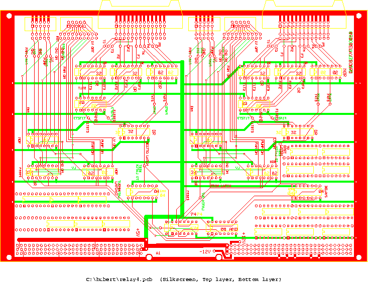
Conversion instructions

The boards have a number of modfications on them by now.


ps version
ps version
ps version


Last update 10 Dec 2000
back