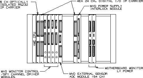
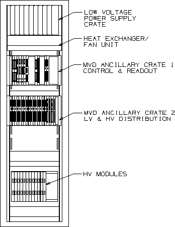
| This is the main MVD ancillary crate. There is plenty of room left.
back ps version |
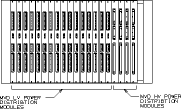
| This is the LV and HV power distribution crate. The units are mostly
passive patch-panel type units. The LV units (4 per motherboard)) have 2
control lines each for turning power off. The crate gets power from the
LV power sullply crate (see below). Cables up to the MVD are described
in the signals document.
back ps version |
|
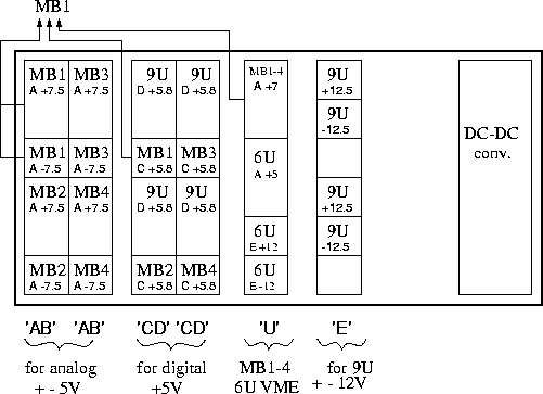
This is the LV power supply crate, a 6U VME crate.. Each double-wide
unit can hold 6
supplies.
Each of the 4 motherboards need +5 analog, -5 analog and +5 digital,
to be conditioned and passed on to the MCM's. In addition, the MB's need
their own +5 power to function. This is shared with the power delivered
to the 6U VME ancillary crates.
'9U' refers to the interface module 9U VME crate, '6U' refers to the two ancillary 6u VME crates. There is one control line per MB, to switch off all power except for the +5 needed to keep the MB itself alive. This is never switched off. |
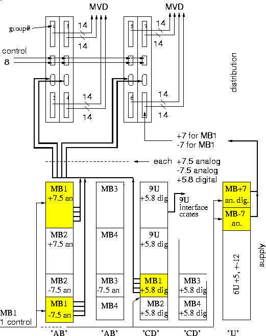
| This is how the power maps from the supplies to the distribution modules
and then up to the MVD.
The drawing is for 1 motherboard only, so this scheme is
repeated 4 times. Each double-wide power supply unit can hold 6
'bricks'. Each distribution unit needs 3 voltages (+5a,-5a,+5d). For Mother
Board 1, the analog
+-5 comes from the top half of the first module, and the +5 digital comes from
a brick in the 3rd module.
The bottom half of module 1 and 3 service MB2, and this is repeated for MB3 and 4 on modules 2 and 4. Each distribution unit splits this power over 2 14-pin ribbons going up to the MVD. Each motherboard needs only 7 ribbons (6 power-comm + 1 daughter board). The 8th 14-pin ribbon will power the motherboard itself (this requires som modifications on the 4th distribution board). The remaining bricks on supply modules 3 and 4 provide +5 for the interface module crate. There is one control line for each of the 14-pin ribbons on the distribution units. Switching off one ribbon corresponds to one power-comm board in the MVD, which holds 6 MCMs.
These are the
specs for the 14-pin ribbon
|
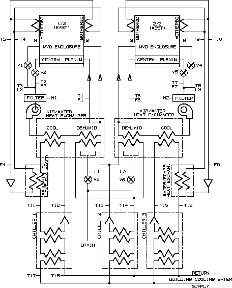
| This is a schematic of the cooling system
back ps version |
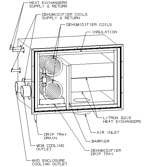
| The heat exchanger box
back ps version |
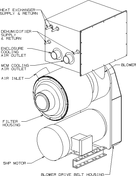
| The air cooling system.
back ps version |
| |
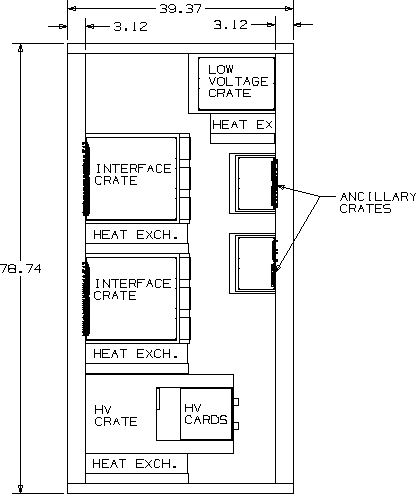
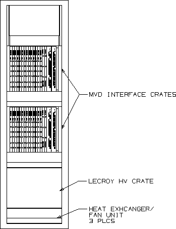
| Above is a side view of the rack where the ancillary-,
interface-, LV- and HV crates are housed.
(ps version)
Below are the front and back views. (ps version, ps version) back | |
| 
|
Last update 30 Mar 01 -- JPS
previous update 18 May 99 - HvH