Useful documents (current as of 2018-12-04)
|
|
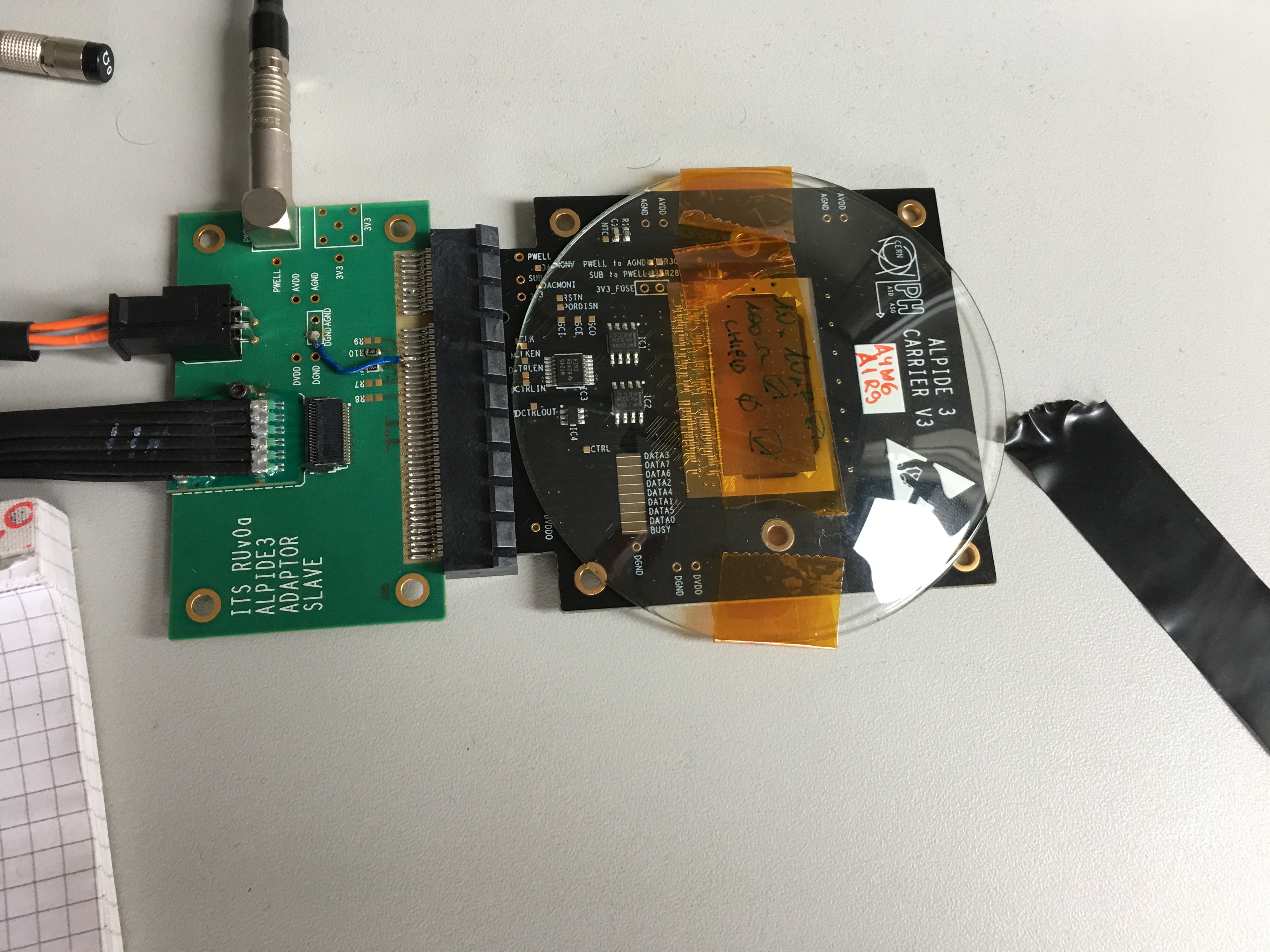
Setup and names of components (all names are Sho's)Carrier board: the ALPIDE chip is wirebonded to this. We have one old one (marked "ALPIDE 3 CARRIER V1" - doesn't seem to work with our current setup) and five new ones ("ALPIDE 3 CARRIER V3"). This board has some jumpers of interest. The top side has "PWELL to AGND" and "SUB to PWELL" which do what you think. The bottom side has R2-R8, which connect DVDD to (probably!) the CHIPID pins on the ALPIDE: no jumper is a 0, a jumper is a 1, R2 is the least significant bit. The old carrier board has CHIPID=16 (R6 present), the new ones all have CHIPID=0 (no jumpers). Since the carrier board is meant to be used with different readouts, there is a lot of stuff on here that we do not use. Adapter board: the carrier board plugs into this. The power/bias connections are made here, and the high-speed signals come off on a thin Samtec cable (with fragile-looking card-edge connectors). This board has jumpers R1-R6 connecting DGND to various carrier board pins. R3-R5 are loaded; these carrier board pins are labeled MCLKEN, DCTRLEN, PORDISN. MCLKEN and DCTRLEN are related to the ICs on the carrier board (which are not active), and PORDISN is probably connected to the POR_DIS_N pin on the ALPIDE. MOSAIC adapter: this is an adapter to convert from the thin Samtec cable to a fat Samtec cable (with big metal connectors and orange tabs). The fat Samtec cable must be plugged into the top connector, the one far from the board. MOSAIC: VME board. The fat Samtec cable must be plugged into the top connector, the one far from the board. There are LEMO connectors for trigger/clock/etc. but we need to solder on some jumpers to enable them (MOSAIC manual section 1.1.3), and I do not see documentation on which connector can be used for what purpose. |
Carrier board (right) and adapter board (left). This is the same carrier board we have, but a different adapter board.
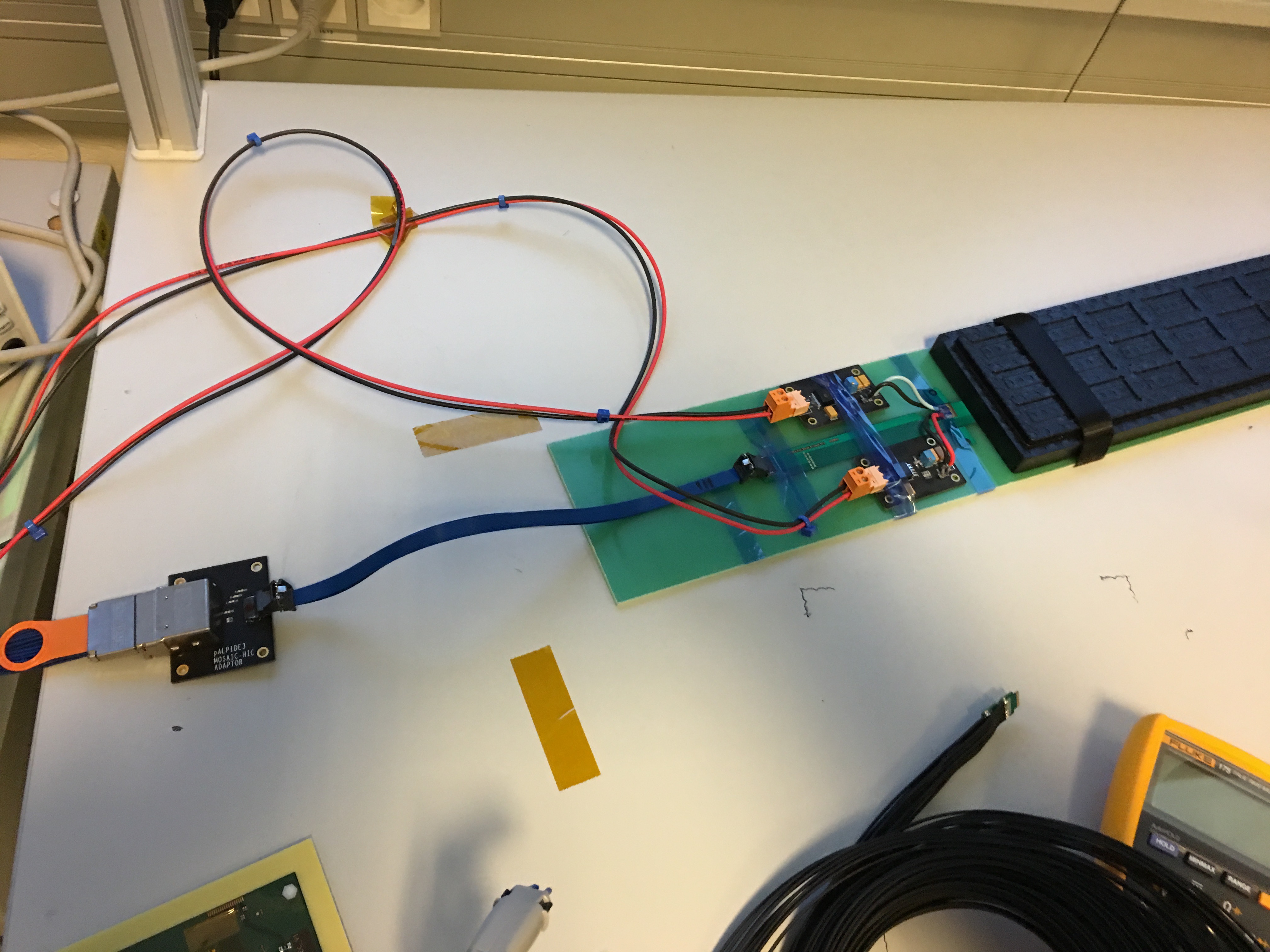
MOSAIC adapter (left) and thin Samtec cable (connecting the MOSAIC adapter to the stave).
MOSAIC boards with fat Samtec cables.
|
Voltages and powerThe adapter board has one big orange 4-pin LV connector (DVDD, DGND, AVDD, AGND) and two LEMO connectors (PWELL, SUB). All of these are wired directly to the ALPIDE chip, so refer to the ALPIDE docs for recommended settings. Since DVDD and AVDD are both recommended to be +1.8V, there is no big problem with running them off the same supply. DGND and AGND are (I think) only tied together on the ALPIDE chip; there is a 2-pin jumper on the adapter board that could be used to tie them together there, but it is unused. Note that PWELL and SUB are shorted together with a jumper on the carrier board - I guess there is no good reason to put them at different voltages. The ALPIDE manual says shorting these to ground is fine for testing, but there are performance benefits (probably reduced noise) to pulling these below ground (up to -6 V) and thereby reverse-biasing the pixel diodes. If you do this, I think you need to change the preamp settings for best performance (I remember seeing this somewhere, but I forgot where). For now we use shorted-out LEMO cables to tie these voltages to ground. |
Recommended voltages:
|
MOSAIC setupThis follows MOSAIC manual section 3. The programs they tell you to use in sections 3.1 and 3.2 are found here. Setting the IP address: this is described in the MOSAIC manual section 3.1. Elena did this - I have not tried it. We are on 192.168.168.250. Firmware: described in the MOSAIC manual section 3.2. Markus recommended that we use the 2016-11-09 image from here. Tests: MOSAIC manual section 3.4 refers to the test software here. I think this is redundant with (and probably superseded by) the "new" software, but it does work, and one of the tests prints the ALPIDE registers which is nice. Tuning the network: With default settings, the network connection is not tuned optimally and that is slowing down data transfer - see MOSAIC manual section 3.3. There are more instructions here. |
|
SoftwareI think Markus sends us tarballs and we put them here. The version that works is bf2489e05358b5ad7f50e9e3cb897af5bc5f19aa-04142017; 299eee0bf6f7afacb369ceee12d9b7b95a8b63bd will communicate with the ALPIDE (slow controls works) but throw lots of errors on all the readout tests. The settings are all in Config.cfg. This is the minimal set of changes to make things run:
|
|
Turning things onTurn on the VME crate. Some of the LEDs on the MOSAIC will turn on - I think "State 3" is steady on, and of the "NIM" LEDs one is steady on and one is blinking. Turn on the power supply (we leave the power switch on and the voltage set to 1.8 V, so just push the "Output On/Off" button). The combined DVDD+AVDD current is about 70 mA at power-on, and rises after the chip is configured. Try running one of the tests (below): test_fifo is what Markus recommended. It seems that on power-on it is random whether or not the ALPIDE responds (this behavior is common to at least two chips, we should ask Markus?), so if the test fails power-cycle the power supply and try again. So far in our experience, if you get the test to work once the ALPIDE will continue to work as long as it is powered. |
|
Slow control teststest_fifo: This is some sort of communications test that (I think) tests the output buffers. test_dacscan: This seems to test the ALPIDE DACs, but the ALPIDE software manual seems to say this only works if you're using the DAQ board. Anyway, it makes some files in the Data directory. test_temperature: This reads the on-chip temperature. |
|
Readout teststest_digital: This applies digital pulses (I think it fills the discriminators directly) and counts the number of hits. This makes a data file, and you can make a ROOT histogram with an included macro. test_threshold: This applies analog pulses and scans the pulse amplitude while counting the number of hits. This makes a data file, and macros are included to fit the pixel thresholds and make a ROOT histogram of the thresholds. test_noiseocc: haven't tried this, but it's supposed to just run the readout, and can be used to measure noise occupancy. This would be the starting point for readout of cosmic events. |
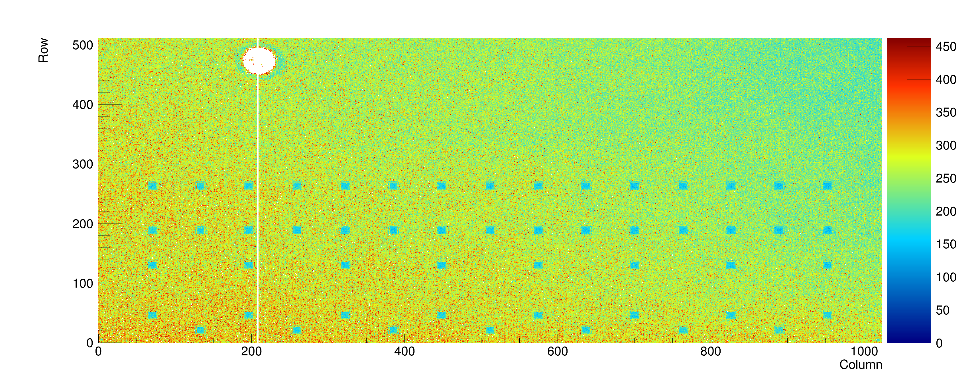
test_threshold output: this was taken in ambient light. I guess the photocurrent changes the preamp operating point, so the metallized wirebonding pads stand out as blue squares. There's also an obvious feature at top left which seems to have screwed up a wide circular region of pixels, and killed a narrow column of pixels (that column also does not respond to digital pulses). Could be dust, or actual damage.
|

Sho Uemura Last modified: Wed Dec 05 18:27:00 MST 2018