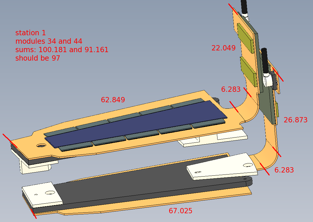
| The station-1 (short) HDIs are 97mm long. In the SolidWorks software,
if the HDI is bent one way, it becomes ~4mm longer, and if bent the
other way, it becomes ~4mm shorter, as shown on the right.
This observation was prompted by work in the assembly lab building
HDI storage jigs.
Fig. 1
| 
|
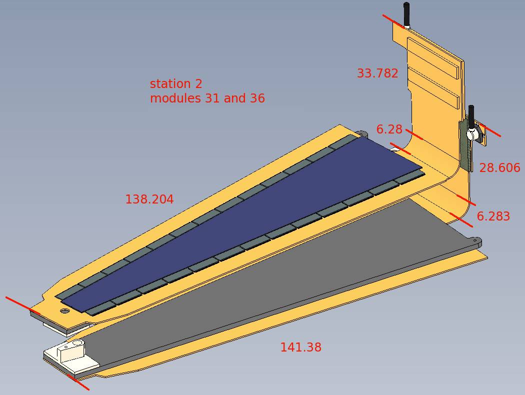
| The long HDIs (stations 2 and 3) sum up to 178.269 and 176.269 mm, while
the actual length is 177mm long.
The difference between the inner and outer arclengths of the 90° bend
is only 0.691 mm, so the observed difference of 2.0 mm is not explained.
Fig. 2
| 
|
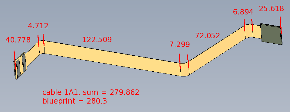
| Unfolding cable 1A1 sums up to 279.862 mm, the blueprint length
is 280.3 mm, so it is probably OK. 1A and 1B are the only straight cables
in the set.
Fig. 3
| 
|
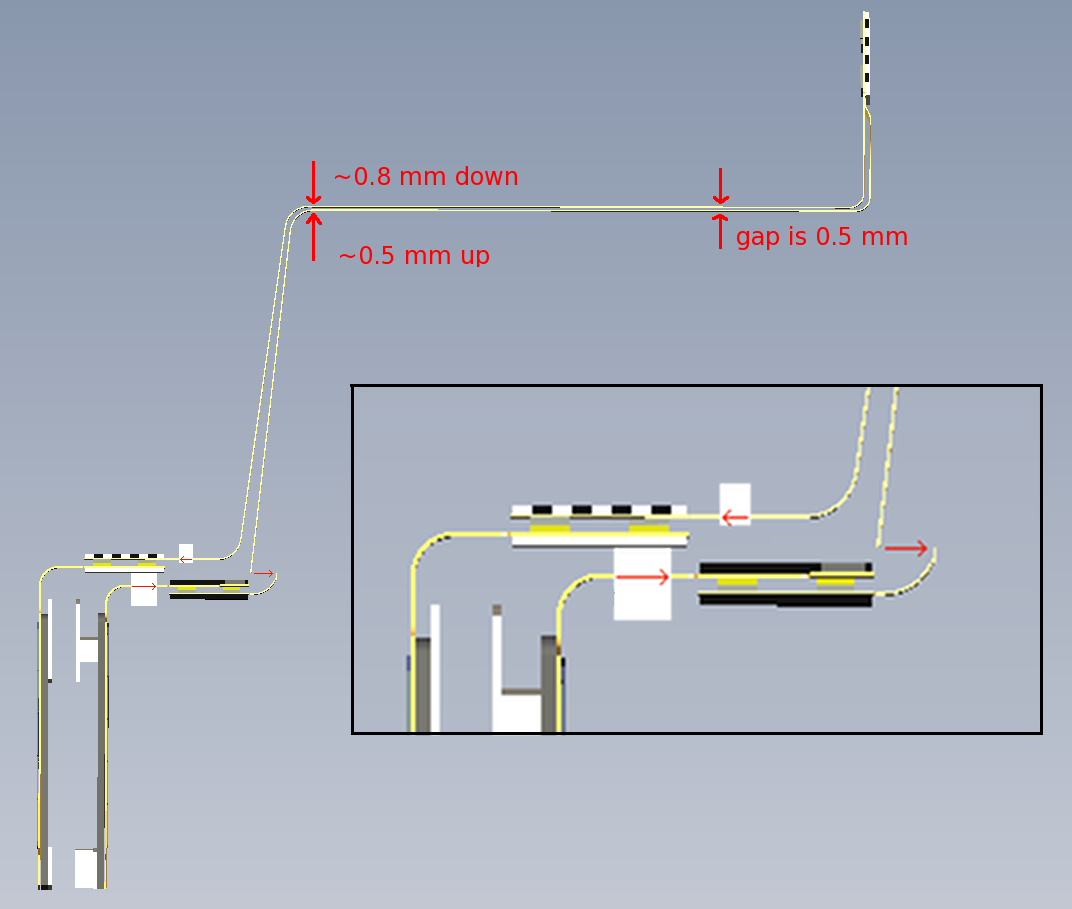
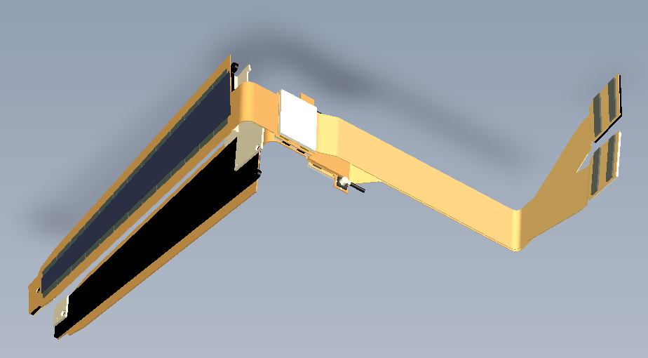
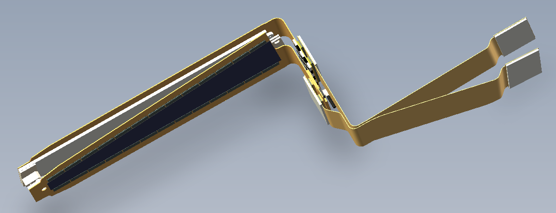
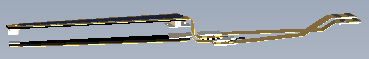
| What happens if we connect the current station-1 extension cables
to the proper-size HDIs? In this figure I have a side view of a pair of
front-back modules (bottom left), and their cables going to the ROC (at
the top right). I moved the connector sections over to
where they are supposed to be (top one 3.18 mm to the left, bottom one
5.84 mm to the right), giving rise to the blank pieces with the red
arrows in the drawing. Then I did some geometry to estimate what would happen
if I reconnected the cables. For the bottom cable, if you angle over the
vertical section to the right, as indicated by the red arrow, and reconnect
it, you have to push it
up by ~0.5 mm. For the top cable, if you swing the vertical section over to the left, and reconnect it, you have to pull it down by ~0.8 mm.
The gap between the cables at the top is 0.5 mm, which is less than 0.5+0.8 mm,
which means that the cables now would touch, and the rest of the movement is
taken up by the bent parts of the HDIs moving up and down a fraction of a mm.
Since the cables are not constrained by nearby objects (cage, station 2), it
looks like we can just use the current station-1 cables.
Fig. 4
| 
|
| This is a pair of station-2 modules plus extension cables. Recall
(Fig. 2)
these were off by about 0.7 mm each. Note that each cable makes a shallow
zigzag as it comes off the HDI. I think we can absorb 0.7 mm in these
zigzags.
Fig. 5
| 
|
| This is a pair of station-3 modules plus extension cables.
The bottom cable makes a shallow zigzag as it comes off the HDI, which
can absorb 0.7 mm of extra slack.
The top cable makes a single 90° bend, and it needs ~0.7 mm more length.
This 90° bend wraps around the station 1 and 2 cables, which also
make a 90° turn here. The gap between each of these cables is 0.5 mm,
so this is not a hard constraint, and we can
pull this cable by ~0.7 mm
Fig. 6
| 
|
| This is a pair of station-4 modules plus extension cables.
Both cables make two zigzags on the way to the ROC. These can take up ~0.7
mm each.
The station-4 HDIs themselves are the proper length.
Fig. 7
| 
|