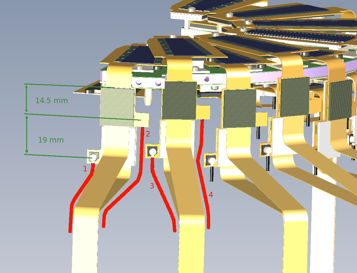
Looking at the top of station1. The cables 1-4 go to the
first ROC board, the next 4 to the next ROC. At this end, cables
1 and 3 are shorter than cables 2 and 4 by 19 mm, and the distance from the
center of the HV connector to the extension cable end is 14.5 mm.
In this view:
     cable type
  -------------
  1    2B  3204
  2    1B  3203
  3    2A  3202
  4    1A  3201
| 
|
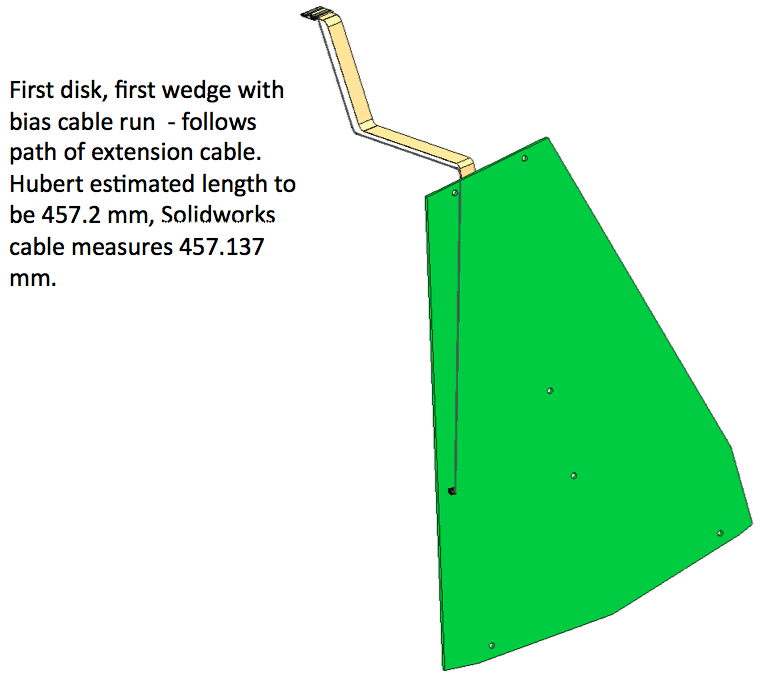
| Assume the bias cables follow the same path as the extension
cables. Note that bias cable 2 follows the straight extension cable
that is highlighted, so we can use it's length for part of the bias
cable path. This is cable
111-PHX-02-3201.PDF, length 280.3 mm.
On the HDI end, the distance from the center of the HV connector
to the end of the cable is 14.5 mm.
| 
|
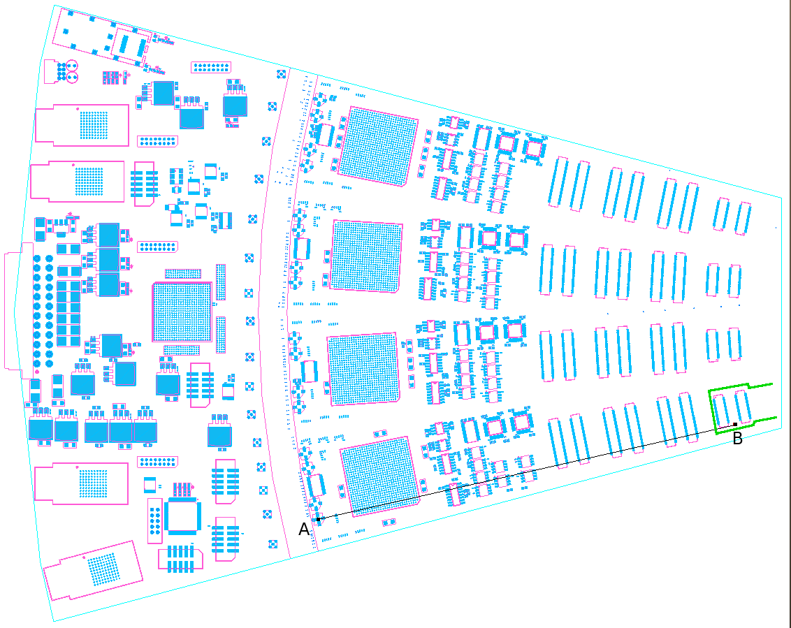
On the ROC end, the distance from the cable end to the bias connectors
is AB minus the distance from the connector's center to the cable end, which is
193-8.7 = 184.3 mm.
      280.3    cable length
      -14.4    Hirose to cable end at HDI
      193.0    A-B on ROC board
       -8.7    half connector
     ------
      450.2 mm
This the connecter-center to connector-center length.
| 
|