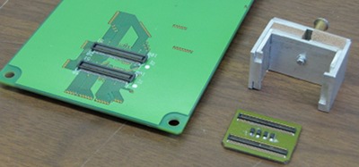
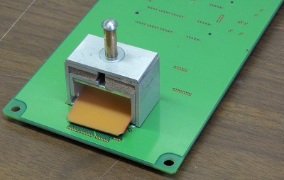
The connector pair comes from the end of a prototype extension cable. The board is a no-longer-used adapter board.
You need some very small files for this.
| (1)
The connector pair comes from the end of a prototype extension cable. The board is a no-longer-used adapter board. | 
|
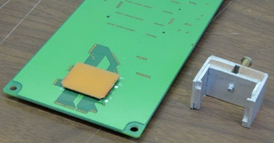
| Connectors in place | 
|
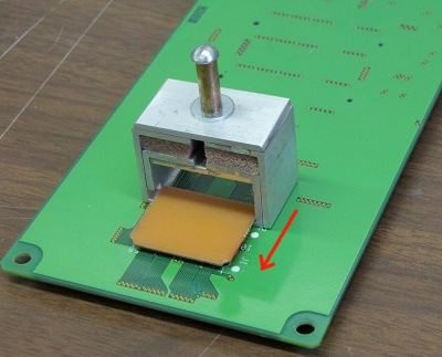
| Slide the extractor over the connectors | 
|
| The center lines of the connectors line up with where the extractor feet split. | 
|
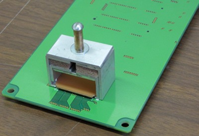
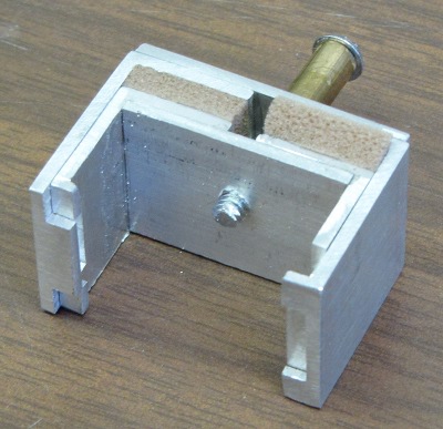
| About 1 1/2 turn of the 8/32 (?) screw (since replaced by a knob) and the connector pops off. The operation was repeaded 50 times, with no damage to the connectors. Also, there were no marks or scratches on the solder mask. | 
|
| You can see the connector feet offset. The footprint of this device is 29×18 mm. Weather stripping foam serves as a spring. Five of these extractors were then fabricated by a local shop for the wide Hirose conectors, and five for the small connectors. | 
|
| A .MOV sequence of the operation. | MVI_0282.mov |
| The lifter was designed for use on the extension cable.
When used with
the HDIs, the HV tab gets in the way, and there are a few small caps in
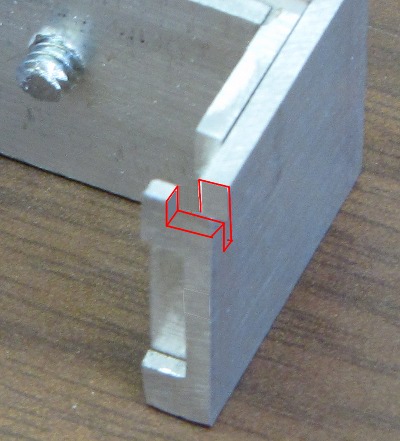
the way also. If you file one corner as shown, you can use it to lift
HDIs either from the extension cables, or from interface boards. You can
see a slot where the HV tab goes (filed in both pieces. Then you file a
little square out of the foot, turning it into a zigzag piece. This is to
clear the caps.
You need some very small files for this. | 
|
| (3)
These tweezers have wedge-shaped teeth that come together to lift off the bias connector without putting strain on the HV tab. [4" long, 6mm wide, 1+mm thick. 4mm folded over, filed into shape] | |