Previous: Bends at 350°F   |   Index   |   Next: Bias connector lifter


Installing ground wires


I made a little holder to work on the wedge ground wires. This one is for the upstream wedges

Bigger

These wedges can be left in the boxes. Just lean the box against the backing, and then the connector end is captured by the edges on the little block

Bigger

Something similar for the downstream wedges, except that for these, you have to take the wedges out of their holders.

Bigger

The connector end is captures by the little blocks.

Bigger

Next I pre-bend the wires. There is a sheet with the bending patterns. Here is a scan of the whole sheet. The pattern for downstream wedges is shown.On the top. you can see there are 2 variations, one for short pedestals where the wire goes around the carbon tab, and one where there is just a little hook that goes into the tab's hole. Red parts are stripped (cut around with a knife blade).

Bigger

First I bend the wire flat according to the pattern, then I twist it into its 3D shape.

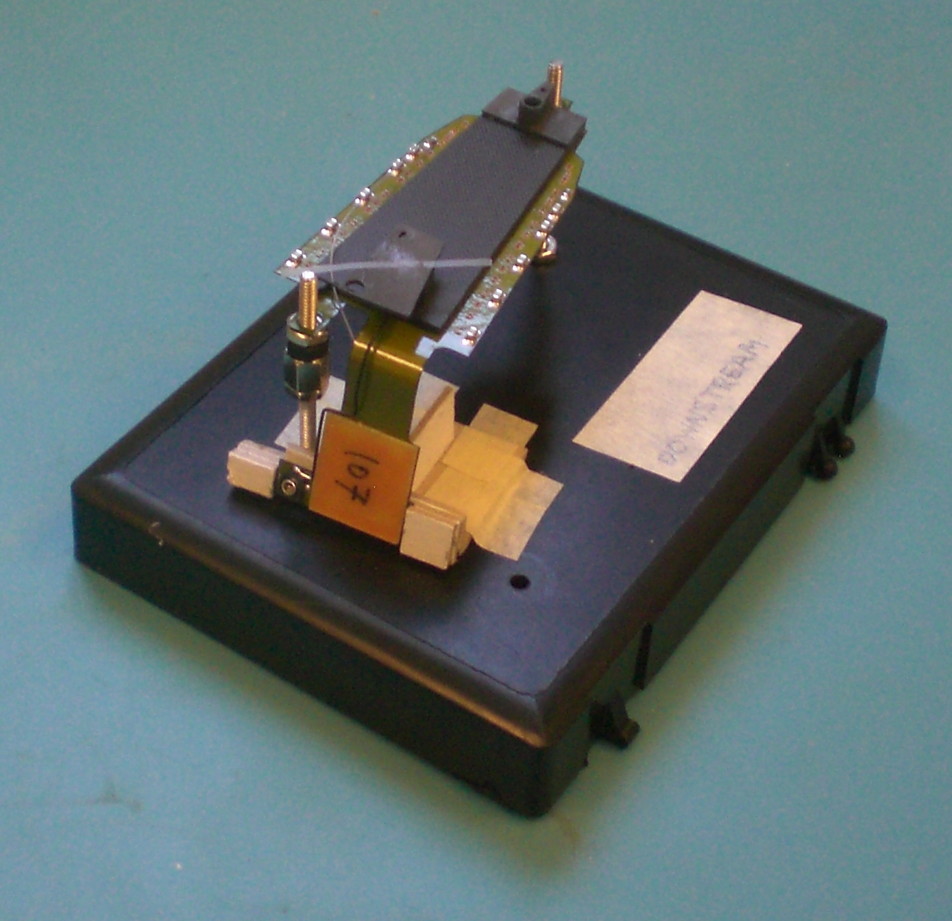
I place it onto the wedge. For the ones that go into the hole, I keep that end in place with a small piece of masking tape. On the connector end, hold the wire in place with the tip of the knife, and solder. In order to not have too much solder, pre-cut the solder into tiny pieces. When you pick one up, you have just enough solder on the tip.

Next you can tack the wire down in a few places. I do not mix these operations (soldering and gluing), since the glue fouls the tip, and you can no longe use it for soldering until you clean it gently.

Bigger


Hubert van Hecke
Last modified: Tue Feb 15 12:23:33 CST 2011