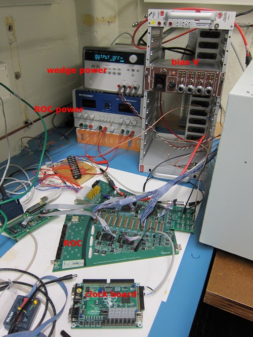
- Bias voltage is 0 Volts
- Wedge power is off
Bigger →
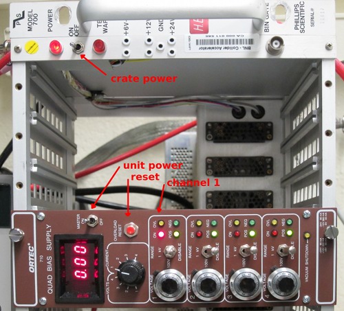
This is the bias power supply. There are 4 output channels, we are using channel 1 (left in this photo. Channels 2, 3, 4 are disabled (see the switches), and therefore the indicator lights are green (safe).
- Verify that the channel 1 knob is turned all the way down
- Verify that the channel 1 switch is in the center (100 V) position
- Verify that the Ortec unit power is off
- Turn the crate power ON
- Turn the Ortec unit power ON - lots of lights come on
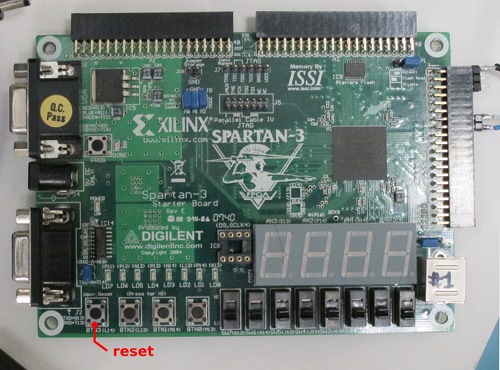
- Push the reset button - channels 2, 3, 4 go green
- Verify that the channel selector is set to CURRENT 1
- Verify that the current reads 0
Bigger →
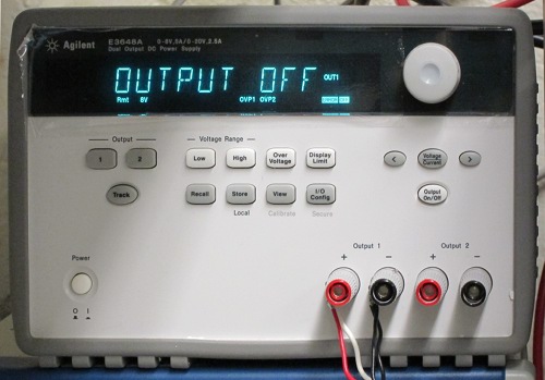
This unit normally stays on, since the OUTPUT ON/OFF state is switched from the GUI (below). When ON, it should read 2.5 V.
Bigger →
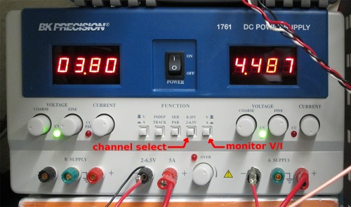
This unit has 2 channels:
- 6.3 V, 0.58 A
- 4.5 V, 3.4 A
Bigger →
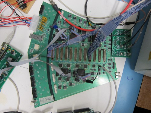
The clock board ...
Bigger →
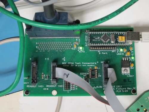
roc
Bigger →
Bigger →
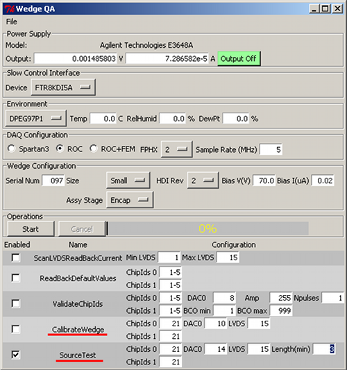
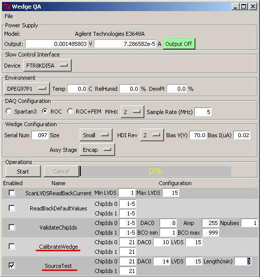
The GUI can be started from the start menu:
- The Output On/Off switches the wedge power.
- Under Wedge Configuration, set the serial number (wedge ID), select small/large, Bias V to 70 V.
- At the bottom, select CalibrateWedge, or SourceTest
- When ready, hit Start. SourceTest takes 3 minutes (settable), and the
CalibrateWedge takes about 45 seconds.
Bigger →
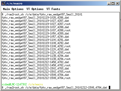
After a calibration run or a source test run, you can look at the results. You have to convert the output .dat file to a root file, with the raw2root.shscript. Files are in /c/e, and they have the wedge ID (here 097) in it, and the date (here 20101212). Tabbing works. Bigger →
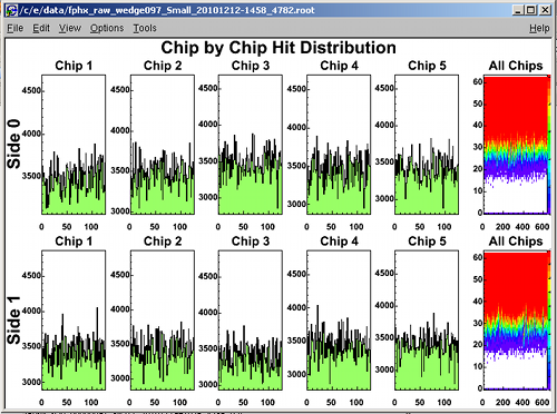
Look at the output - fire up root: 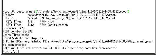
Bigger →