next up previous
Next: User Interface Up: MVD FEE Test Hardware Previous: DAC Serial Ports

FEE Boards Serial Signals

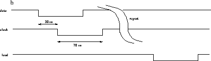
These are the serial lines labeled SR1 and SR2 in figure 1 Figure 6 shows the timing of the mode bits serial signals.

  
Figure 6: Timing of the SR1, SR2 serial signals


Converted to HTML from LaTeX by Christine Jarmer
Wed Feb 7 14:57:50 MST 1996