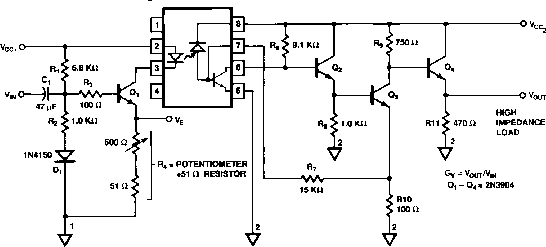
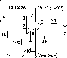
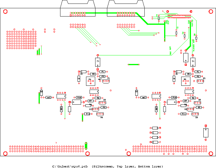
This board takes in the 40-pin ribbon coming down from the MVD.
Here is the relevant cable in the signals document. It arrives on a 40-pin
0.1"×0.05" connector. The digital I/O signals for the
custom ADC readout are split out to a 16-pin 0.1"
connector, and the digital signals that do the switching for the
spy line readout
are split out to a 14-pin 0.1" connector.
The fast analog spy line signals are sent through a 17-MHz optically isolated
optocoupler chip
and then a
clc426 driver
drives the BNC coax to the control room. The CR side of the circuit gets power
and ground from the CR.
spy line driver chip,

|

|
| ps version | ps |
|
The circuits were tested by using a 1.3V square pulse as input.
Values in the table are in volts. |
| |||||||||||||||||||||||||||||||||||||||||||
| parts list (for 4 boards +1 spare ): | |||||
|---|---|---|---|---|---|
| per circuit | +per board | total | have | ||
| optocoupler chip | Agilent HCPL-4562 | 1 | 10 | ||
| op amp | Nat.Semi. CLC426 | 1 | 10 | ||
| transistor Q1-4: | 2N3904 | 4 | 40 | ||
| diode D1 | 1N4150 | 1 | 4 | 30 | |
| cap C1,2,3 | electrolyte 47 uF | 3 | 1 | 35 | |
| R1 | 6.8 K | 1 | 10 | ||
| R2,12 | 1.0 K | 2 | 10 | ||
| R3,10,13 | 100 | 3 | 30 | ||
| R4 | 51 | 1 | 10 | ||
| R6 | 9.1 K | 1 | 10 | ||
| R7 | 15.0 K | 1 | 10 | ||
| R8 | 1.0 K | 1 | 10 | ||
| R9 | 750 | 1 | 10 | ||
| R11 | 470 | 1 | 10 | ||
| R14 | 33 | 1 | 10 | ||
| potentiometer | 500 | 1 | 10 | ||
| connector | 0.1" 14-pin right angle | 2 | 10 | 10 | |
| connector | 0.1x0.05 40-pin r.a. 3M 81040-5502-3 | 1 | 5 | ||
| connector | VME backplane | 2 | 10 | 10 | |
| connector | BNC feedthrough | 2 | 10 | 10 | |
| lv connector | (burndy) | 1 | 5 | 5 | |
| sockets | for 8-pin chips | 2 | 10 | make | |
| front panel | 1 | 5 | |||
| pins for ADC protocol | ||
|---|---|---|
| name | on MVD ribbon | on 16-pin to I/O |
| sclk | 3 | 1 |
| sdata in | 5 | 3 |
| sdata out | 7 | 5 |
| SSTRB | 9 | 7 |
| ADC_A0 | 8 | 9 |
| ADC_A1 | 10 | 11 |
| ADC_A2 | 12 | 13 |
| ADC_A3 | 14 | 15 |
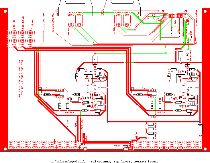
| ps version |
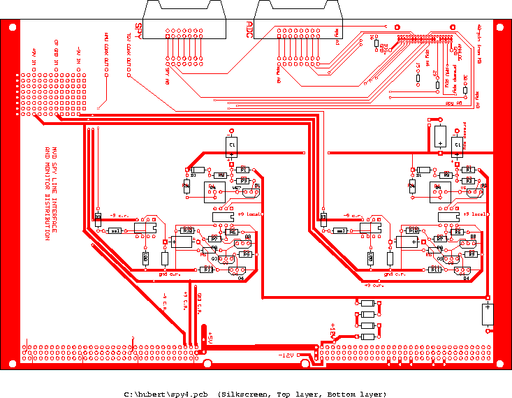
| ps version |
| ps version |