 ps version
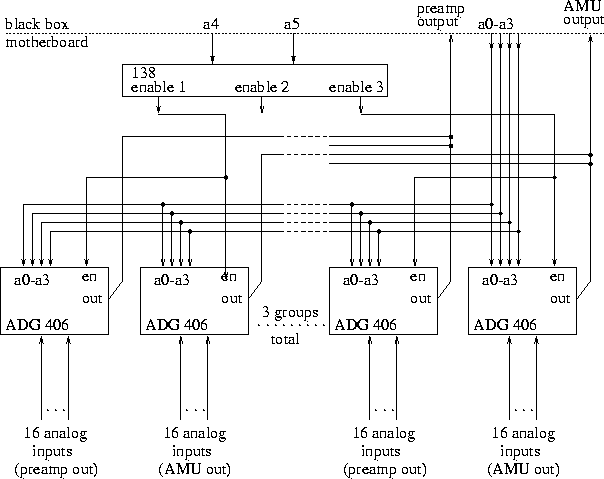
Each MCM has 2 spy channels, one at the preamp output and one at the AMU output, for a total of 2x42 analog channels per MVD motherboard (of which there ar 4). We propose to use Analog Devices ADG46, which are analog multiplexers. They take 16 inputs, and connect one of these to the output, depending on the value of 4 switch bits (a0-a3), and on the level of the enable line.
Shown below is the proposed arrangement for 1 motherboard. There are 3 pairs of multiplexers (2 pairs are drawn), each pair sharing an enable line, since we always want to look at the preamp and AMU signals from the same MCM. Thus an MCM is selected by setting the appropriate levels on a0-a3, and on a4-5 which in turn set enable 1,2 or 3.
 ps version
As shown on the preceding page, the analog signals are put onto Glink and sent to the control room, whre they are un-converted.