This snippet of code from svx_ifvtx looks like it is designed to do the right thing,
judging by the comments:
do istation=5,12 ! make a rotation matrix for each station irot = irot + 1 ! such that all face in the same direction, irsh(istation) = irot ! and phi=0 starts at y=0, and goes positive. CALL GSROTM( irsh(istation), & 90., 90. +stag_ang(istation)*abs(stagger), & 90., 0. +stag_ang(istation)*abs(stagger), & 180., 0. ) enddo | |
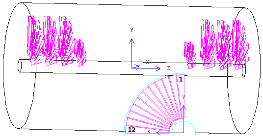
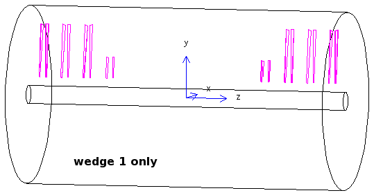
However, drawing just wedge #1 shows it to be on the top, and if I
draw more wedges, they rotate from +y to +x, that is counterclockwise, as
shown in the inset.
I had also noticed earlier, that the staggering went in the negative-φ direction. |
|
I changed the rotation matrix to be
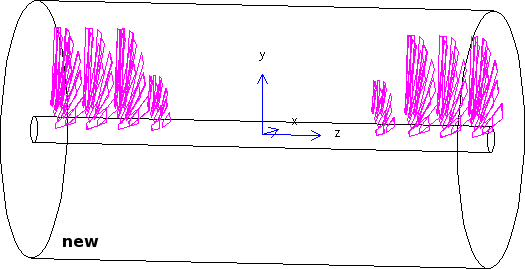
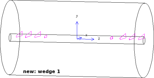
90, 0 + stagger 90, 90 + stagger 0, 0Which is the null rotation, save for the small staggering angles. You can see that wedge #1 is now along +x, and drawing the first 12 wedges fans them in positive φ |
|
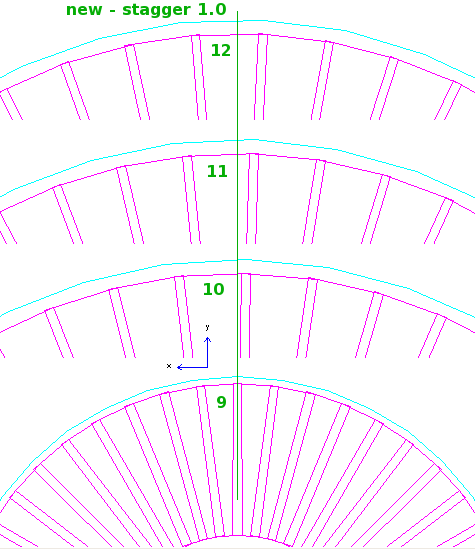
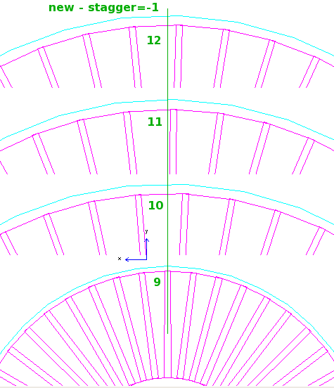
There is a small difference in the arrangement as compared with before: the figures show a cut through the silicon, normal to the x-axis, and 17 cm from the origin. This cut just catched the tips of the silicon of the big disks. You can see 2 silicons per plane, one on the front, and one on the back of the disk. In the new arrangements, these are not the same ones, but the ones that are staggered on the same side of the support disk. This is why the green dashed lines don't line up between the old (top) and new (bottom) figures. | |
this shows the staggering for stagger=1.
Looking out from the IP, the small disk (9) is not rotated, and the successive big disks are rotated in +φ by increasing amounts. Note that before this fix (15 oct 08), the staggering was in -φ. | |
this shows the staggering for stagger=-1. |