gif
jpg
png
How to build Pisa from scratch:
Step-by-step
Previous sections (1) through (13) here.
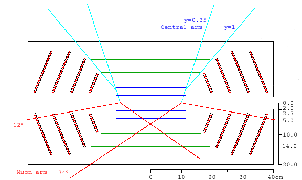
In the drawing below, a blue line is drawn at angle y=1, along the edge of
layers 2,3 and 4 of the barrel. The first two silicon endcaps are reduced to
start 1 cm
away from this line, in order to allow for support structures, cooling
services and power and signal cables. Also in blue are lines indicating the
central arm acceptance. On the bottom half, red lines indicate the muon arm
acceptance for an 'interaction diamond' of z=+-10 cm.
See
newendcap_2.html or
review_jan05.html
for more details.
|
Formats available:
gif jpg png |

|
|
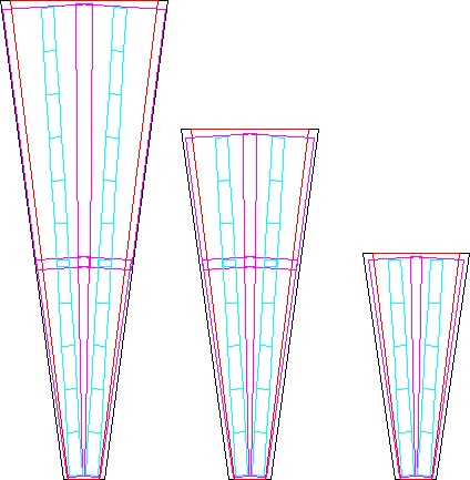
There are now 3 different endcaps. The panels that make up the lampshades
(24 per shade) are shown here. The size of the new small panel is determined
by the size of the inner silicon (pink).
formats: png, gif, jpg |
|
||||||||||||
| These are cross sections of the panels, with the vertical scale stretched by ×4. You can see the support panels in the middle of each (black), then standoff strips (red), the readout chips (black) and the silicon (pink). | 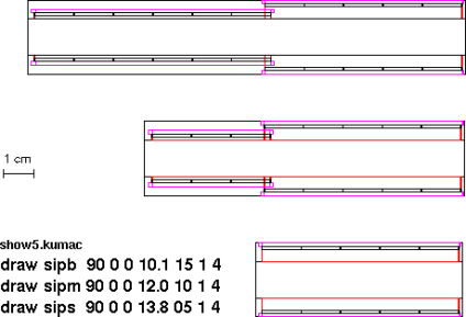
| ||||||||||||
|
Note that in order to get enough clearance between the small lampshade and the 3rd barrel layer, the small shade was moved out in z. formats: png, gif, jpg | 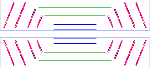
|
| Support structures are added in the cone-shaped area between
the endcaps and the barrel layers (blue). Notice the two red disks supporting the barrels
in this figure. These were in there from the past, left over from when the
strip layers (green) had the same z-extent as the pixel layers (blue).
These red supports are now removed from the code.
png gif jpg svx_09feb05.f phnxSili_09feb05.par | 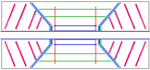
|
| Actually, I took the old supports and transformed them into support rings at the end of the ladders. At the end of the ladders, there will be mass for the liquid-cooling tube connectors, some mounting bracket to connect the ladder to the carbon panel lampshade that is the actual support structure, and also a bracket to hold the cable (strip or pixel bus) to the ladder and fold it upward. For now in made this 5×5 mm Aluminum. | 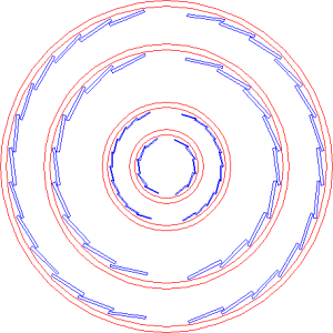
|
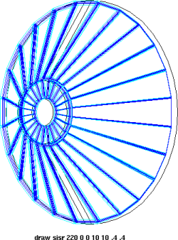
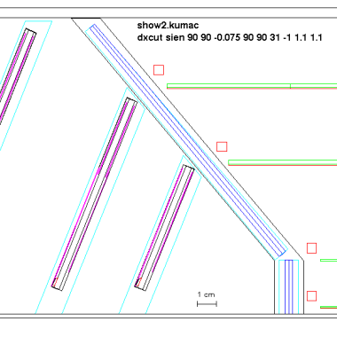
| The support structure lampshades have a 24-fold symmetry. A cross-section detail is shown. The red squares correspond to the support rings (5×5mm). | |
| 
|
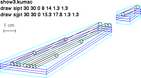
| Inside each panel of the support lampshade (light blue) are two 2-mm carbon-carbon
support panels of the frame (dark blue), and cooling tubes going to barrel layers 1-4.
Since there is no direct correspondence between the number of ladders in layers 1-4, and the 24 panels of the support lampshade, I made the following approximation (numbers per half-barrel):
| 
|
|
The '-2' in the table above means I don't place tubes in 2 of the wedges, 2 on top and 2 below. This closely matches the barrel layout. The result is is a distribution of cooling tubes that is very close to the real one. In addition, I rotated the shades (including the SI endcap lampshades) such that there is a seam along the vertical. | 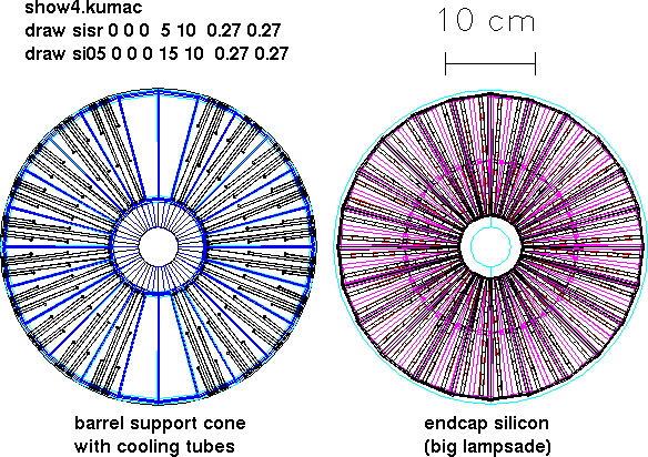
|
Info taken from Hiroaki's January 2005
presentation.
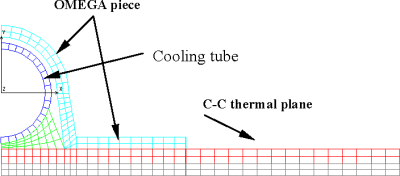
Bottom to top:
From the
Hytec report:
Cooling tube: 3mm ID with 0.2mm wall thickness.
glue: typical 75 um
Omega piece: 0.4mm thick (compression-molder resin composite)
Panel: 900 um thick
(17) Cooling tubes on the barrel layers
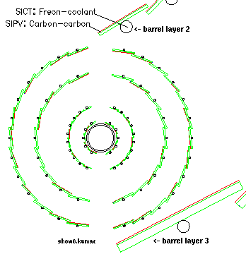
I added 3mm diameter cooling tubes to the barrel. For layer 1
this is a big fraction of the ladder mass. The tubes are made of 'Freon-coolant', which for now is C5F12. I also changed the support
material of the ladders to Carbon-carbon.
Next: crosschecks by running PISA
back