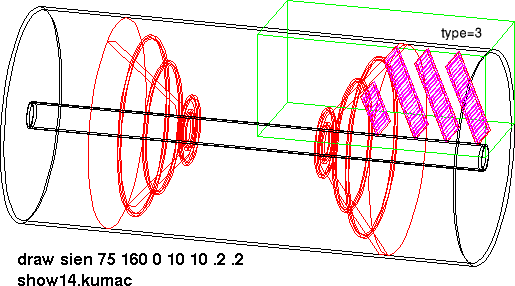
| This picture from the simulation shows the 4 planes inside the overall volume. The red rings are the supports at the ends of the central barrel pixel (2) and strip (2) layers (not shown). The first plane has 12, and the next 3 layers have 12 8-chip pixel modules. |
|
| This is a closeup view of the first pixel plane. There are 2×6 silicon strips, each 73.6 by 6.4 mm, 250um thick, with 5.6 mm gaps in between. The center-to-center spacing of the front 6 and back 6 strips is 2mm. The bottom edge of the Silicon is 35mm from the nominal beam axis. Each pink strip is an '8-chip module'. | 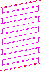
|
| Distribution of the number of electron-hole pairs created along the path of 5 GeV muons, sprayed randomly from an event vertex at z=0. Mean is 17000 | 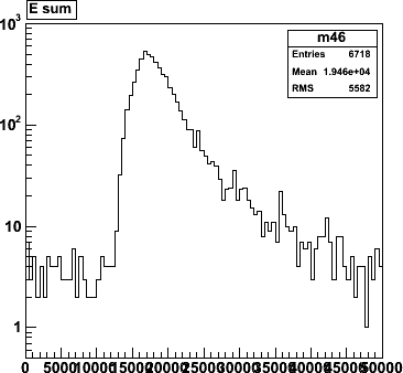
|
| The silicon is divided into 50× 400um pixels (with the long dimension in the horizontal direction.This si the distribution of electrons per pixel, in all hit pixels. There is a peak at 15K electrons, and lots of structure below it. | 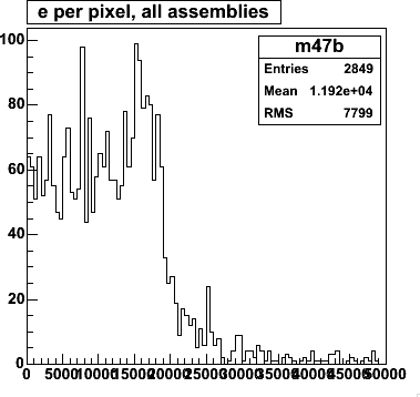
|
| This is the number of electrons seen, as in the previous plot, with
the strip number (1-12) on the vertical axis. The beam axis is 3.5cm below
strip #1.
Pulseheights of 16K electrons are seen in he lower strips, but the maximum pulseheights go down to about 8K electrons per pixel in strip #12. | 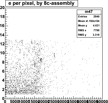
|
| The effect seen in the previous plot is caused by the fact that in the higher strips, tracks come in at an angle, and the total pulse height is divided over severalpixels, such that the signal per pixel goes down. This scatter plot that the number of pixels in a cluster goes up from 1 in the lower modules to 4 or 5 in module 12. You can also see that there is minimum around module 3, where track come in perpendicular to the silicon. | 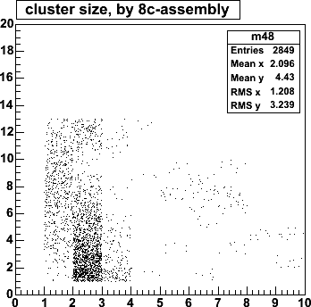
|
| The mean cluster size is about 2, with a long tail a few orders of magnitude down. | 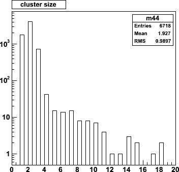
|
| This shows the hit pixels for a single AuAu event, in the first layer. The red lines are boundaries between the 12 8-chip modules in this layer. (for this diplay, the modules have been spaced out vertically a bit, that's why you don't see any overlaps.) | 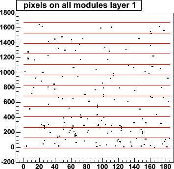
|
| Number of pixels hit in the first layer, module 1, the busiest 8-chip module in the detector. The mean is 23, which corresponds to an average occupancy of 0.1%. | 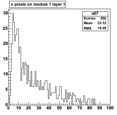
|
| hit rate | (picture) |
| For the big DOE detector, we have an algorithm that does 2-D
tracking in the r-z plane. For the pixel detector this algorithm works fine for tracks
in or near the vertical direction, where the geometry is roughly equivalent to
having the ministrips in the horizontal direction.
However, if we use this same r-z algorithm for tracks near the horizontal direction the resolution would be very bad, since the equivalent strip width would be 400 um. For these horizontal tracks, we have good resolution in the plane transverse to the r-z plane, with a smooth transition between the two cases for angles in between. For now, we will use the existing r-z code, with a cut on track angle to limit ourselves tracks to near the vertical plane, until a full 3-D tracking code is developed that can make full use of the pixels. | 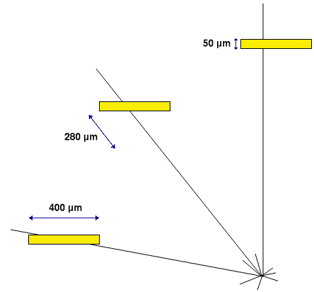
|
| The maximum angle in the real device is nowhere near 90°. if we require that 4 planes be hit, then the highest angle is seen for a track that just hits the bottom of plane 1 and the edge of plane 4. If plane 4 is 3.5cm wide at z=36cm, it crosses plane 1 at 19.4cm at x=1.9cm, as seen in the top view. In the x-y plane projection (front view), this track makes an angle φ=28° with the vertical, and the 'effective strip width' along this line is about 200 μm. | |
| vertex resolution: vertex resolution: for now, the resolution is the same as for the 50-um strip big (DOE) detector.This figure is taken from those studies | (picture) |
| z-vertex resolution, when only tracks within 10° of the vertical plane are used. This resolution is the same as for the big lampshades, as it should be. (plot by Xiaorong) | 
|
| If tracks at all anglea are accepted, the average resolution is worse, because of the pixel orientation effect described above. (plot by Xiaorong) | 
|
| bla | 
|
| bla | 
|