In phnx.par, sili_endcap_config=1 selects this configuration.
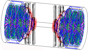
In phnx.par, sili_endcap_config=2 selects this configuration.
In phnx.par, sili_endcap_config=3 selects this configuration.
(1) phnxSili.par is no longer needed. In the past, we needed a separate par file so we could shrink the beam pipe and the hHelium bag when turning on the SVX. Now, this can be done in pisa.kumac, on the GEOP line:
GEOP 'ENDC' 'CENT' 'PIPN' 'NOSE' 'PLUG' 'BCOL' 'HBGN' 'PHSH'On this line, PIPN means the new (smaller diameter) beampipe, PIPE would be the current (<2009) beampipe. Similarly, HBGN is the smaller Helium bag, avoiding the SVX and the big readout wheels, HBAG would be the current one. By switching this way, a separate file phnxSili.par is no longer needed, and we can use the standard phnx.par.
(2) The code in CVS directory /simulation/pisa2000/src/svx/* is used to simulate the silicon barrel detector, and in the endcap region either the FVTX detector, consisting of 2×4 disks of ministrips, or 4 stations of pixel planes. Up to now all these options were constructed in a single large file svx.f.
| Files: |
svx.f svx_fvtx.f svx_ifvtx.f svx_fvtx_old.f phnx.par |
In the new versions, the code in svx.f constructs only the barrel, the common support structures (including the endcap cages), and the big wheels. There are calls from svx.f to separate routines, switched by sili_endcap_config in phnx.par: 1 = svx_fvtx.f, 2 = svx_ifvtx.f or 3 = svx_fvtx_old.f.
The new FVTX code has silicon made from 6" wafers, big enough to cover the
radial span, whereas
the old geometry had silicon detectors made from 4" wafers, and was
divided in two along R. The logical structures for old FVTX, new FVTX and new
IFVTX are as follows:
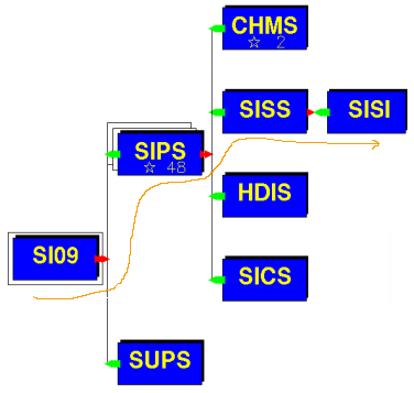
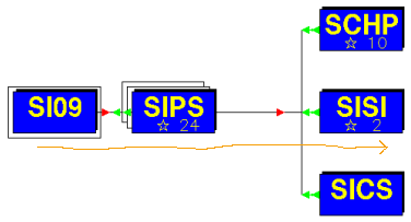
| In the new geometry, SI09 (10,11,12) are the small (big) disks.
These contain 48 panels SIPS (SIPB). Each of these contains silicon SISS
(SISB), of which SISI is the sensitive part.
In phnx.par, sili_endcap_config=1 selects this configuration.
|
|
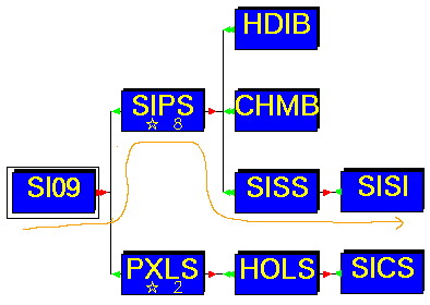
| For the IFVTX, the structure is maintained. Small (big)
stations are again SI09 (10,11,12), which contain 2×4 (2×10) 8-chip modules
SIPS (SIPB), which contain
silicon SISS (SISB), of which SISI is the sensitive part.
In phnx.par, sili_endcap_config=2 selects this configuration.
|
|
| Logical structure for the old geometry. SI09 (SI10,11,12) is a small
(big) disk. It contains 24 small (big) panels SIPS (SIPB), and each small
(big) panel has 2 (4) silicon detectors SISI on it.
In phnx.par, sili_endcap_config=3 selects this configuration.
|
|
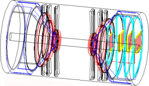
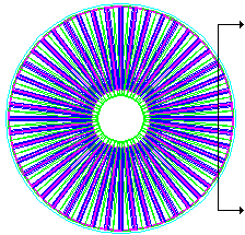
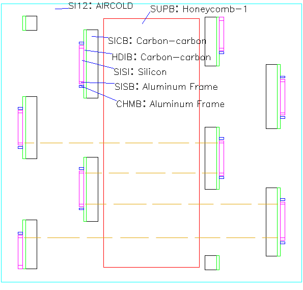
| This is a cross section in the y-z plane of one of the big IFVTX stations.
The horizontal dimension is stretched by ×10.
The mother volume SI12 contains 2 PC boards PXLB, each 0.1" thick. the boards have a hole HOLB, into which is mounted the TPG panel SICB, set to 0.5mm thick for now (CHECK). On each board are mounted 10 8-chip moduless SIPB, also shown enlarged in the inset. The stackup consists of 270μm HDI in dark blue, 250μm thick CHMB, which are the readout chips, and on top 250μm silicon. Volume SISB in lignt blue is all silicon, and magenta SISI inside of this is the sensitive part. The PC boards face each other, and are offset in the vertical direction such that there is a 0.6mm overlap of the sensitive silicons SISI. | 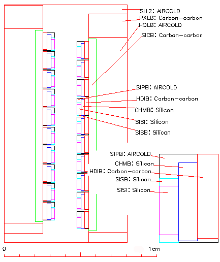
|
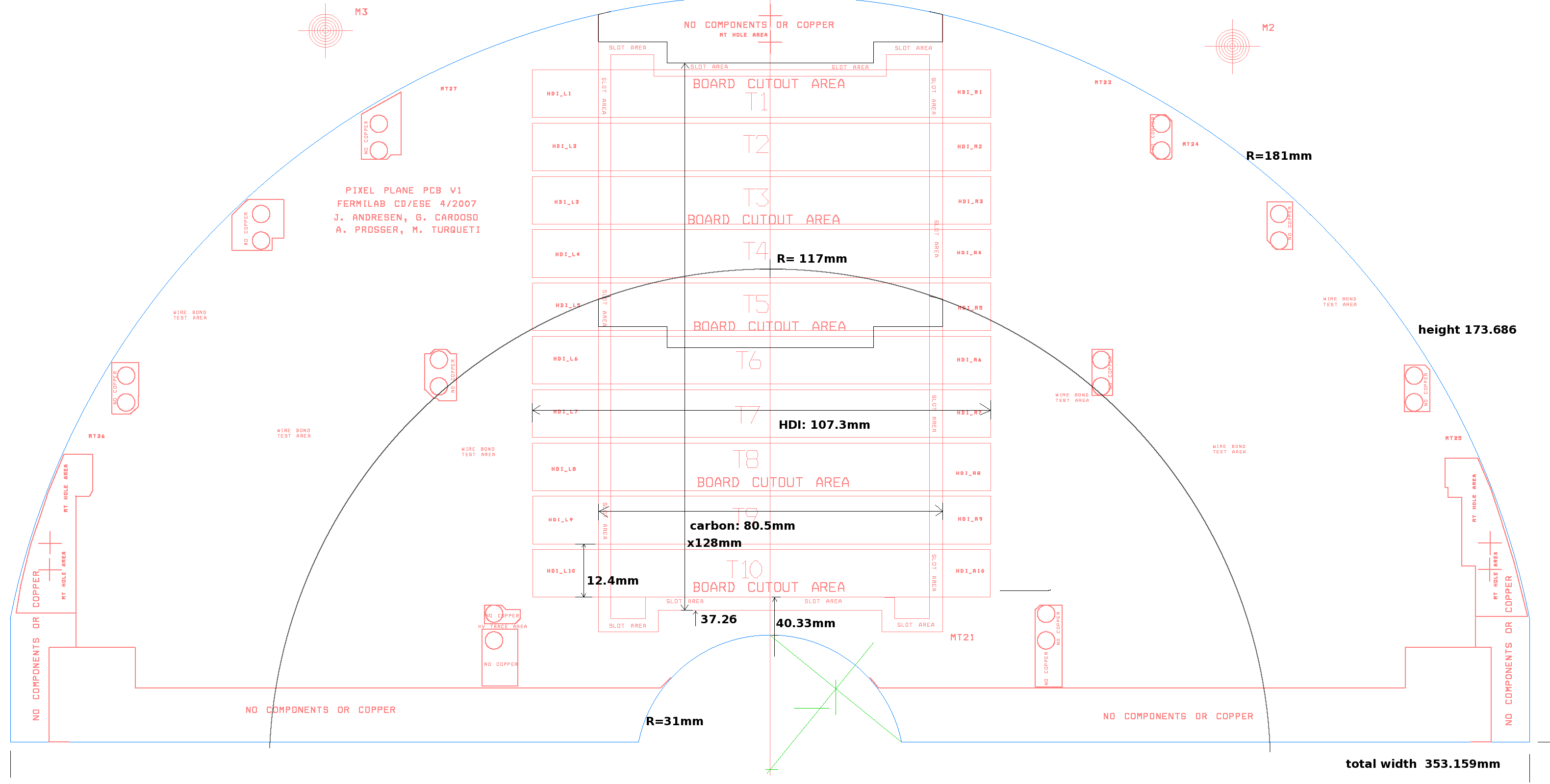
| Some dimensions of the above model are taken from this drawing.
[3.00mm spacing, 1.46mm spacing, 0.6mm overlap, 12.4mm repeat].
QUESTION: the HDI-FPHX-Silicon stack is 770μm thick; how is this partitioned?
More measurements taken from
this figure: | 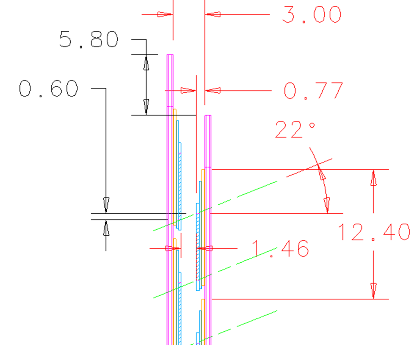
|
| Front view of the PC boards (red). The fvtx cage is in brown. The figure shows that the offset boards fit inside the cage. | 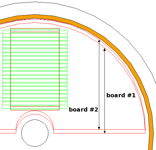
|
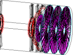
This is a cross section of a big disk, a straight cut close to the edge of the disk.
The horizontal scale is stretched by ×10. The brown dashed lines indicate that the sensitive silicon
is hermetic in phi (with no overlaps), and repeats every 4 wedges. There actually will be a 1mm overlap,
which will be fixed in the next release.
| 
|
| Following my suggestion, layers 3,4 of the barrel were modified so that the ladders were perpendicular to the radius vector. | 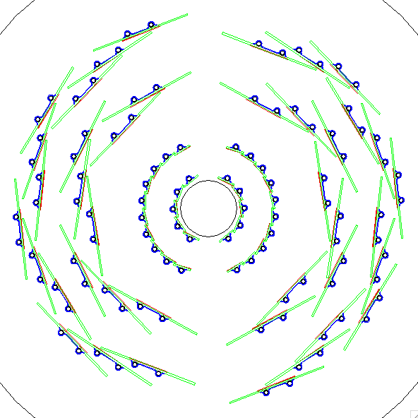
|