| After discussion with Jan and Walt, the last of the flat planes 
was moved to z=36 cm, which leaves a few cm for services in the back. Planes
SI09 and SI10 stay the same, and SI11 is again placed halfway between 
10 and 12. 
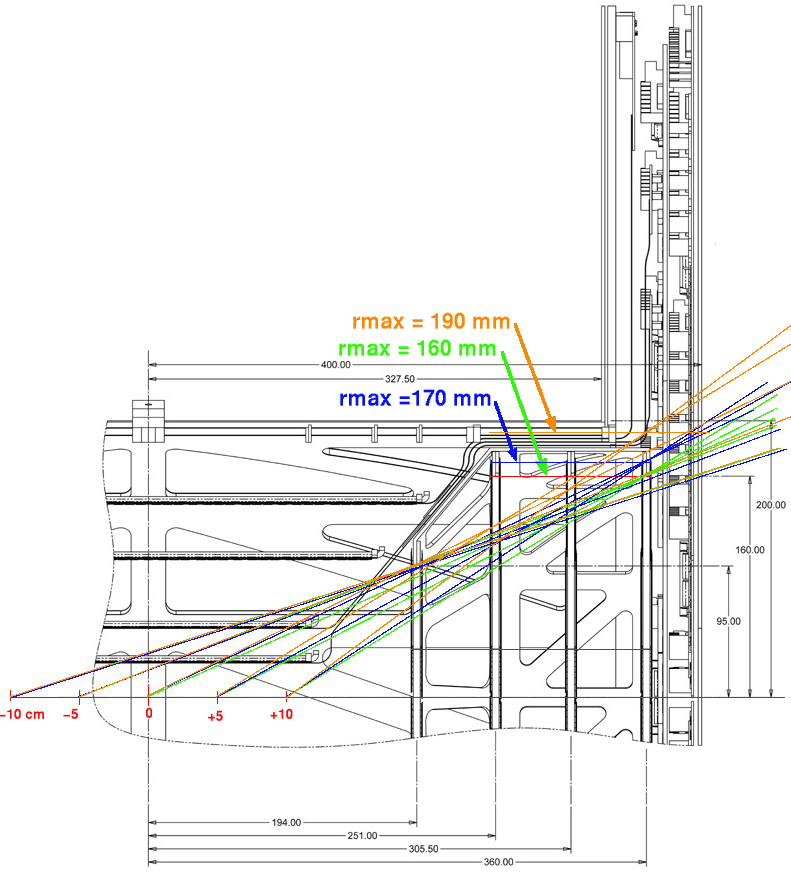
Old positions here: phnxSili_flat_27feb06.par  
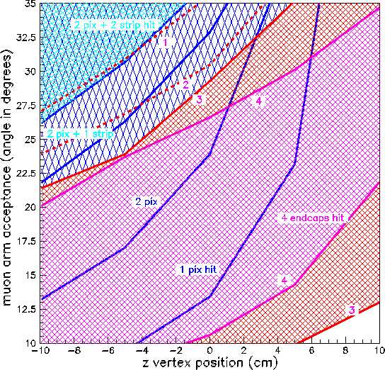
The top red line shows the maximum angular acceptance for an event at z=-5cm and requiring 4 planes, the bottom red line the minimum angle requiring 3 planes, for an event at z=+5 cm. |   | 
| Note that by moving the last 2 planes inward we improve the acceptance around 24-28° a little bit. requiring 3 or 4 planes. |   | 
| This is the acceptance plot for the new geometry. For numbers, see the
    plotting script Red and pink lines and shades are endcap boundaries, blue are the barrel boundaries. Here is the same plot for the cone configuration. |   | 
| Update June 2006: This is a working drawing showing proposed positions of endcap layers, with nominal radii of 16 cm. This is before we negotiated some extra radial space. The colored lines show which of the 4 endcap layers define the acceptance envelope for different z-vertices. |   | 
| This plot summarizes the acceptance, for tracks that hit all 4 endcap 
       layers, for  the 3 cases shown above. acceptance_jun06.kumac |   |