Bigger →
Bigger →
Bigger →
How:
Unzip Dyconex files from here:

Extension Cable Design Files From Dyconex February 22, 2011
to www/phenix/fvtx/construction/cabes/feb11/, this makes subdirs
380437-440 through 380449-452, and single-cable subdirs 380437a-380452a
below that.

Use the gerbv Gerber viewer, turn on the surface pad and outline layers,
export as 3201-3504.pdf. This is done at 400 dpi, or 157.48 px/cm.

Open Hytec cable drawings, from
Release Drawing Packages of Extension Cables (10-September-2010)
Unzip to www/phenix/fvtx/construction/cables/feb11/hytec/

This makes many files per cables, I use
'111-PHX-02-3xxx - Check Plots - 6 To 1 Scale.pdf', sheet #8, and import
at 400 dpi.

Overlay top left, check perimeter, and go to bottom right.
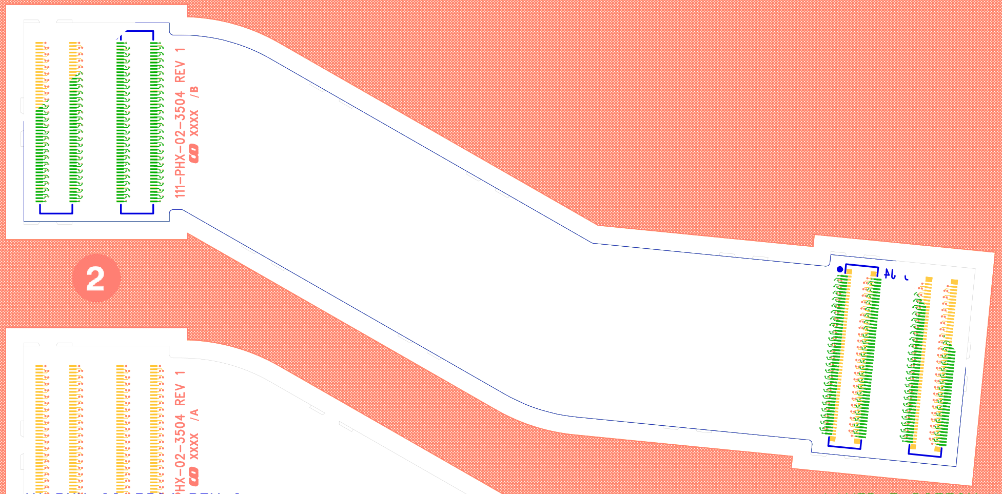
| Overlay the plots. In this image, the gerber background is
orange, the connecter pads are yellow, and the outline is in light
gray. The Hitec overlay has black outline, and green pads.
Bigger → |
|
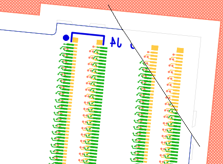
| The images are matched on the top right. Here I cut away a
corner from the Hytec overlay. You can see the perfect alignment of
the gray and black outlines, and the way the pads line up. This is the
HDI end. The HDI's connectors are male, and have a narrow width (4mm)
footprint. The matching female connectors on the extension cable are wider
(5 mm). These wide footprints appear on both the Gerber and the Hytec
versions.
Bigger → |
|
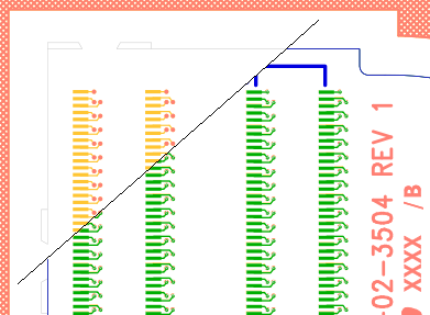
| On the bottom right, you can see that the mechanical outlines
match up perfectly, but the Hytec drawing has the wide (female, green)
connector footprint drawn, whereas the Gerber (yellow) has the male
(narrow footprint), which is correct.
Bigger → |
|
Type (1A-2B) is how the cables can be identified in the 3D model. Gerber is the gerber files directory, e.g. 437 = 380437a. Disk is position on the disk. Opp/same is whether the connector pairs are on the same or opposite side of the cable. Orientation checks for mirror image problems. Outline overlays Gerber with Hytec.
| # | type | gerber | disk | opp/same | orientation | outline |
|---|---|---|---|---|---|---|
| 3201 | 1A | 437 | front | neutral->ok | ok | ok |
| 3202 | 2A | 438 | back | same ok | ok | ok |
| 3203 | 1B | 439 | front | neutral->ok | ok | ok |
| 3204 | 2B | 440 | back | same ok | ok | ok |
| 3301 | 1A | 441 | front | opp. ok | ok | ok |
| 3302 | 2A | 442 | back | same ok | ok | ok |
| 3303 | 1B | 443 | front | opp. ok | ok | [1 px long] |
| 3304 | 2B | 444 | back | same ok | ok | [2 px long] |
| 3401 | 1A | 445 | front | opp. ok | ok | OK |
| 3402 | 2A | 446 | back | same ok | ok | [1 px short] |
| 3403 | 1B | 447 | front | opp. ok | ok | [1 px long] |
| 3404 | 2B | 448 | back | same ok | ok | [1 px long] |
| 3501 | 1A | 449 | front | opp. ok | ok | ok |
| 3502 | 2A | 450 | back | same ok | ok | [2 px short] |
| 3503 | 1B | 451 | front | opp. ok | ok | ok |
| 3504 | 2B | 452 | back | same ok | ok | ok |