Cable geometry checks
In the drawings below, Roger's cables are in gray, and Dave's are in light blue for the outline, and green for the connector solder masks.
You can click on the drawings to get the full size
OK | 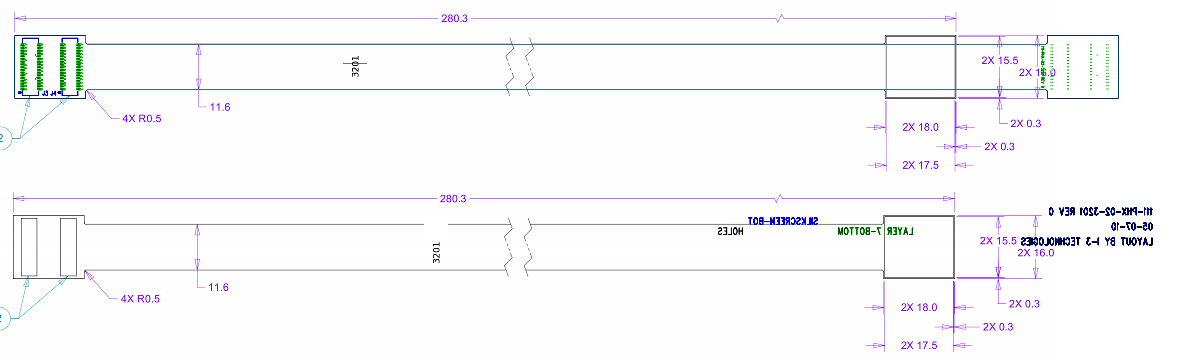
| ||
| Station 0 type 2 (3202)
3202_both.xcf
OK | 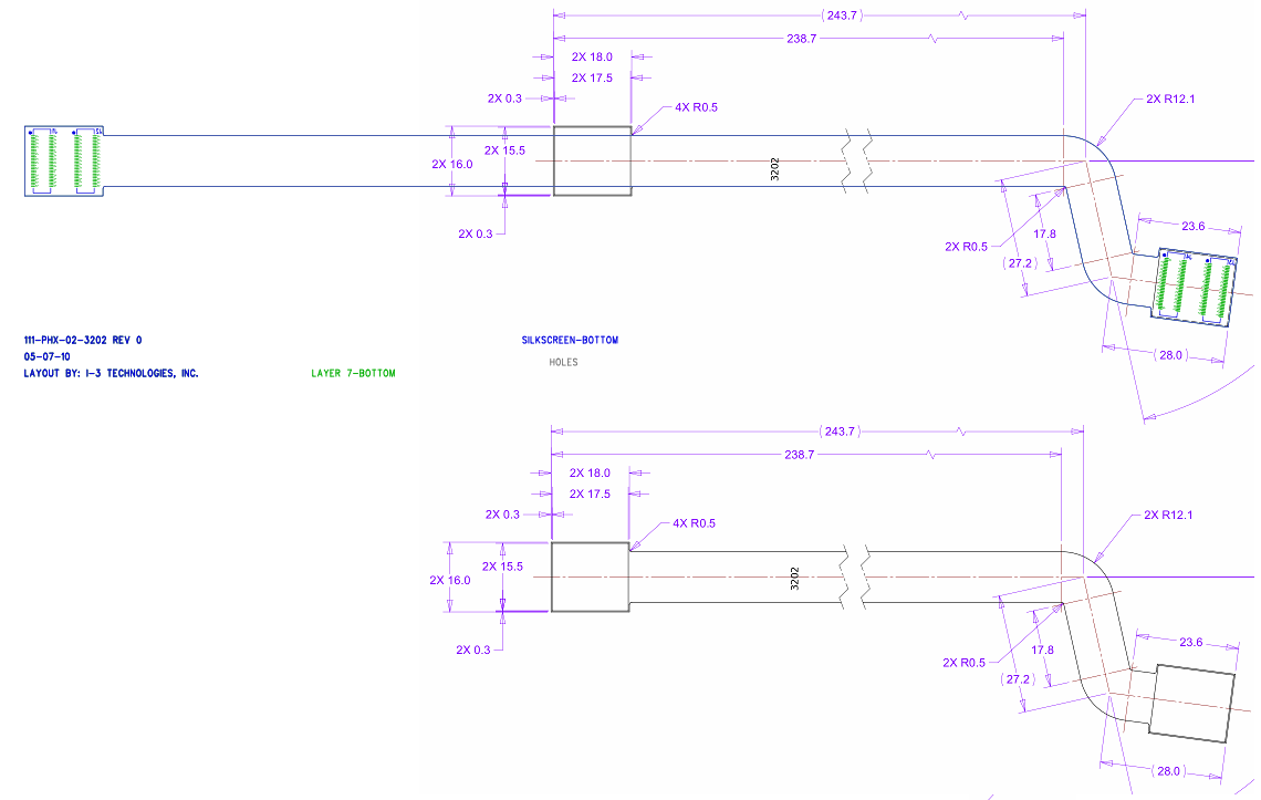
| ||
| Station 0 type 3 (3203)
3203_both.xcf
OK | 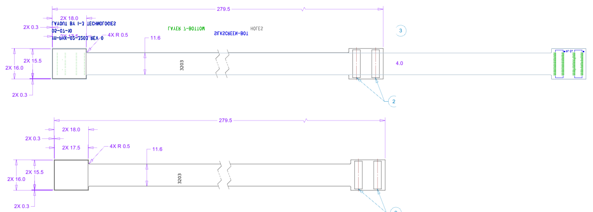
| ||
| Station 0 type 4 (3204)
3204_both.xcf
OK | 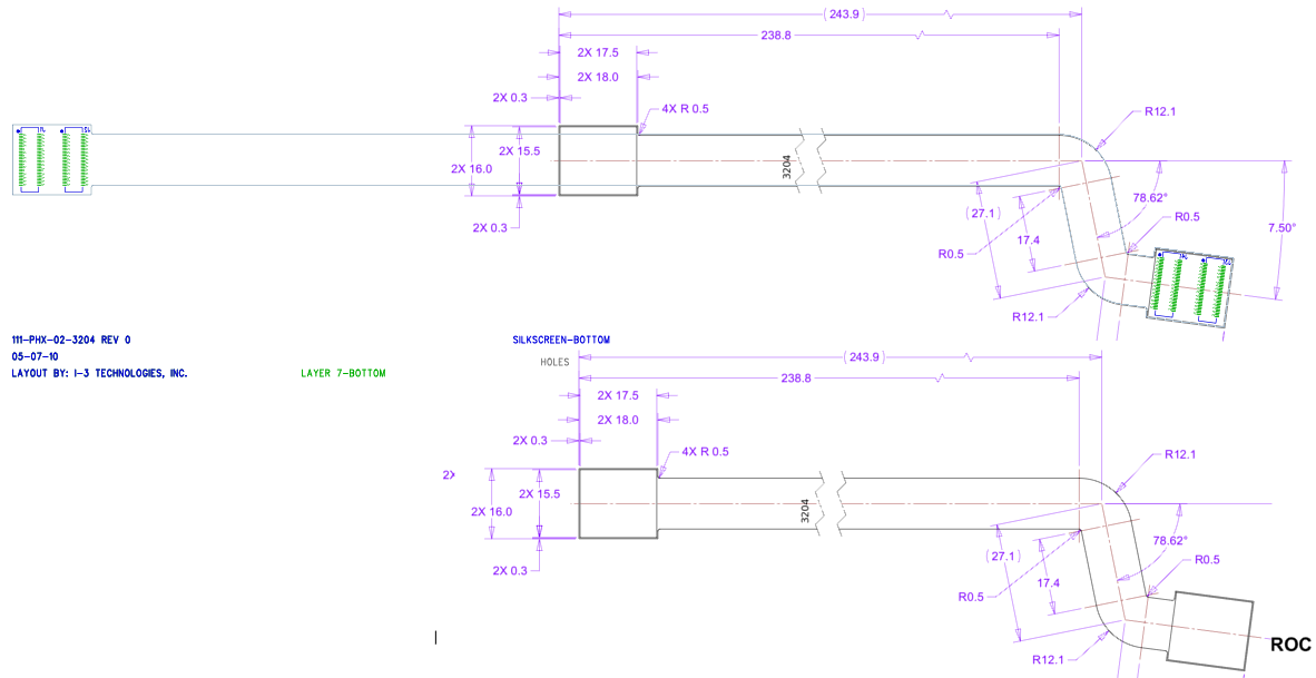
| ||
version 1: 1.06 mm too long | 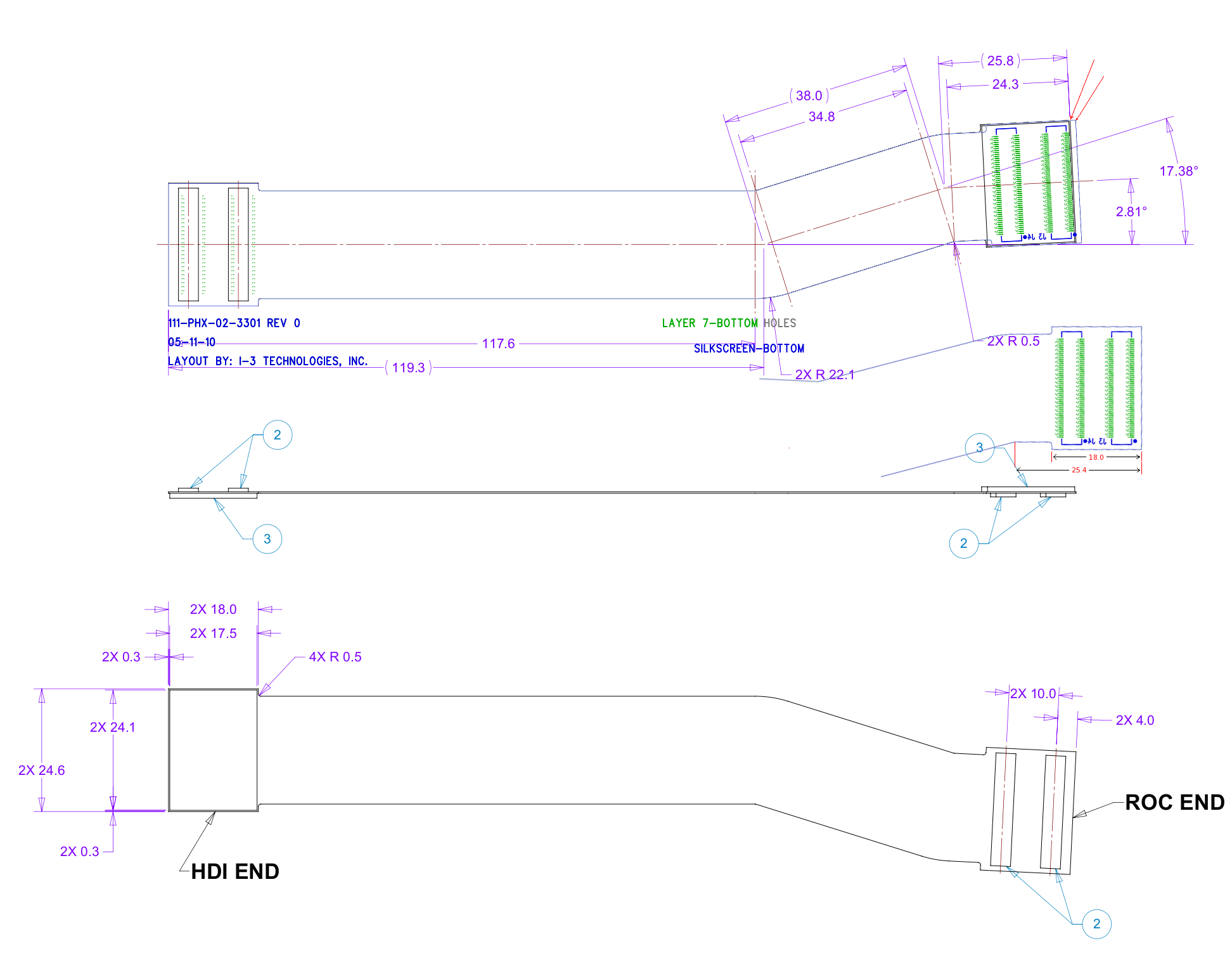
| ||
version 2 (20 May): OK | 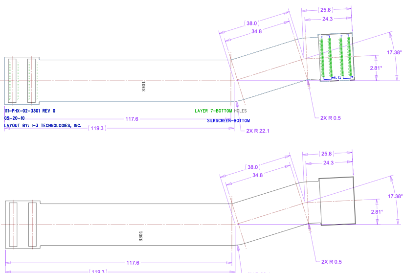
| ||
| Station 1 type 2 (3302)
3302_both.xcf
OK | 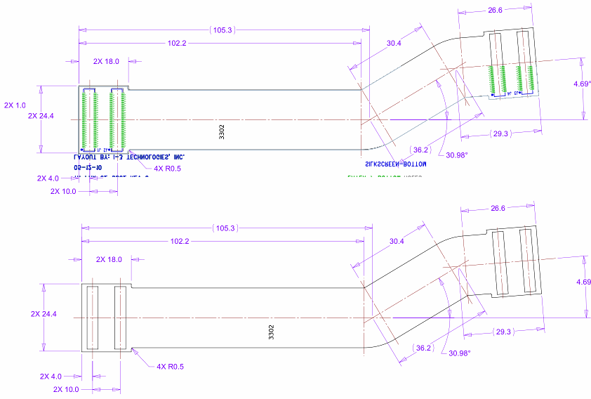
| ||
| Station 1 type 3 (3303)
3303_both.xcf
| 
| ||
| Station 1 type 4 (3304)
3304_both.xcf
OK | 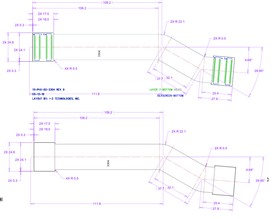
| ||
OK | 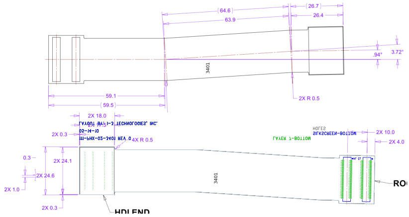
| ||
| Station 2 type 2 (3402)
3402_both.xcf
OK | 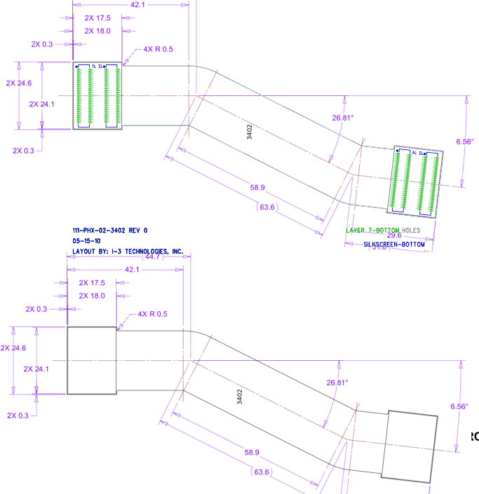
| ||
| Station 2 type 3 (3403)
3403_both.xcf
OK | 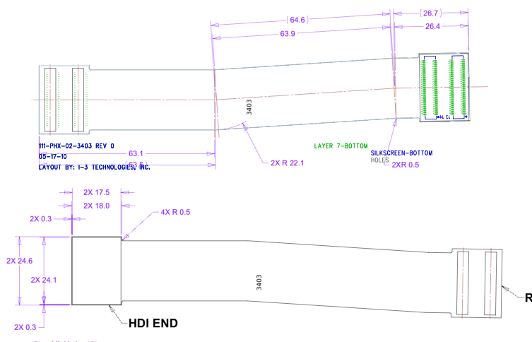
| ||
| Station 2 type 4 (3404)
3404_both.xcf
OK | 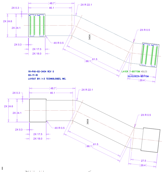
| ||
| 
| ||
| Station 3 type 2 (3502)
3502_both.xcf
| 
| ||
| Station 3 type 3 (3503)
3503_both.xcf
| 
| ||
| Station 3 type 4 (3504)
3504_both.xcf
| 
| ||
May 2010 Hubert van Hecke