(2)
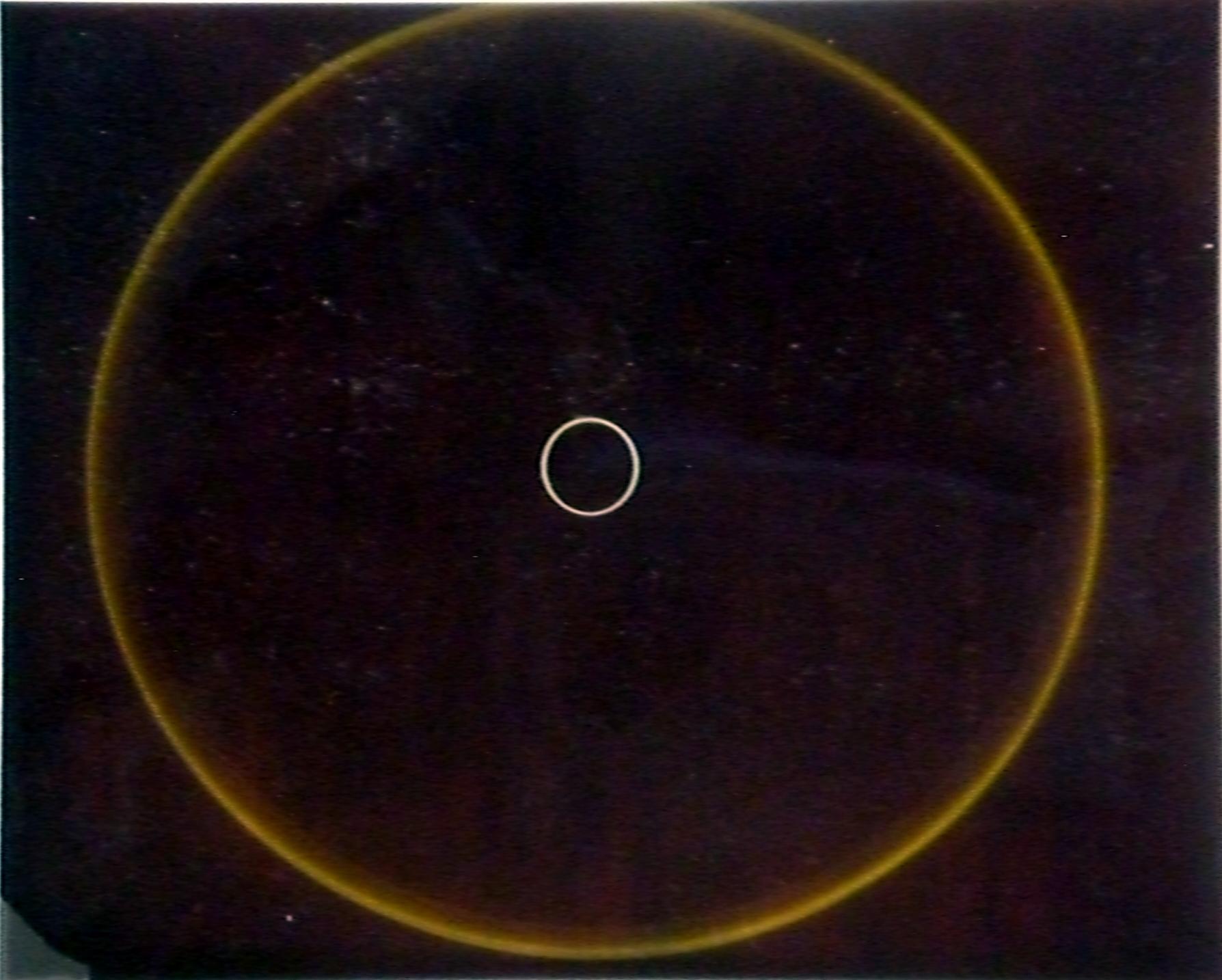
This shows the conceptual arrangement of a generic imaging Cherenkov detector.
A particle incident on the radiator (yellow) emits photons at fixed angles
with respect to the traveling direction. A focusing element (a lens or
mirror, green) focuses the light into a sharp ring centered on the optical
axis (since the incident particle in this case is parallel to the optical
axis. The ring is detected by a (pixelated) detector (black) in the focal plane.
The incident particle may also produce a hit at p in the readout plane.
Note that the distance d between the radiator and the lens is irrelevant,
and can be reduced to zero.
| 
|
(3)
The device is shortened so that the lens (green) is up against the radiator, and
we have enclosed all elements into a box with the same cross section
as the radiator (blue). These boxes can be stacked to make a wall.

For particles incident parallel to the optical axis, rings are
centered on the
optical axis. The ring position gives the direction vector of the
incident particle, and the particle hit gives a 2D coordinate.
| 
|
(4)
For particles that come in at an angle, or for particles
very close to the boundary, some of the Cherenkov photons will hit the wall
of the box and will be lost, leading to inefficiencies.
Make the walls of the box out of mirroring material (green lines, top
and bottom), and no photons are
lost
| 
|
(5)
In these cases, portions of the rings are reflected onto the image
plane, but these can be
unfolded to recover the full rings.
| 
|
(6)
Units like these can be stacked into a relatively shallow
wall with projective geometry.
| 
|
Radiator material choice: This would be aerogel with a refractive index
around 1.020. Plotted on the right are the Cherenkov angles for pi and K
for different refractive indices n.
(7)
Assuming we can distinguish ring radii if they differ
by >10%, we can identify kaons up to 5(8)GeV if we use aerogel with
index of refraction 1.020 (1.010).
So this argues for using low-n aerogel.
|

|
| 
|
(8)
What to use for readout? We need to match the Cherenkov spectrum which rises with
smaller wavelengths, with the optical properties of the lens and the reflective
surfaces, wich typically have cutoffs at small wavelengths,
and with the photon detector in the focal plane. Most importantly, the Rayleigh scattering
properties of the aerogel determine what can be achieved.
Let's examine the spectrum of photons produced in a 3 cm slab of aerogel.
The figure on the right
(taken from
this writeup) shows the transmission spectrum (the histogram) of a
block of aerogel, 3 cm thick. No photons below 300 nm make it through the
block unscattered.
The solid line fit is to the function
 , where A is the asymptotic transmission value at
high wavelength, and C (for 'clarity') is a measure of the quality of the
aerogel. , where A is the asymptotic transmission value at
high wavelength, and C (for 'clarity') is a measure of the quality of the
aerogel.
| 
|
(9)
The left panel shows the (simulated) spectrum of produced Cherenkov photons, fit to
 . On the right are the spectra of scattered
and unscattered photons, for different values of C, 0.0050, 0.0100, and 0.0200.
The green spectra show that for higher clarity aerogel (lower C), there are
more unscattered photons available, and the spectrum is shifted to lower
wavelengths. . On the right are the spectra of scattered
and unscattered photons, for different values of C, 0.0050, 0.0100, and 0.0200.
The green spectra show that for higher clarity aerogel (lower C), there are
more unscattered photons available, and the spectrum is shifted to lower
wavelengths.
The bottom plot, with C=200e-4, is representative of aerogel available in the early 1990's. The middle plot, with C=100e-4, is typical of currently availably
aerogels. The top graph represents the lowest value of C that has been
reported.
So for currently available aerogel, the spectrum peaks in the 300-500 nm region.
| 
|
(10)
In these plots you can see that for an imaging Cherenkov counter using aerogel, many of
the photons that arrive in the detector plane are produced close to the exit face of the
aerogel, which means there is an upper limit to the useful thickness of the aerogel radiator.
| 
|
(11)
Sensitivity of PMTs peaks around 400 nm, and extends to lower wavelengths depending on the
photocathode type. Acrylic transmission cuts off below 300 nm.
So we're looking for a photon detector with sensitivity in the 300-500
nm range.
| 
|
(12)
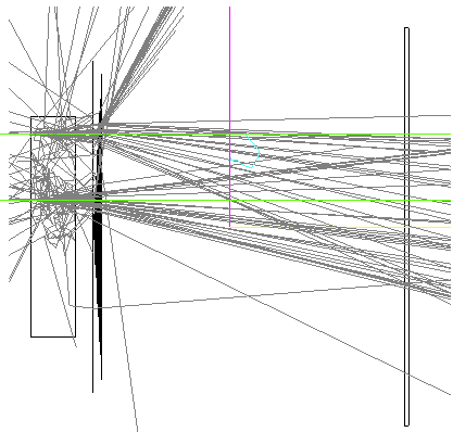
Geant-4 simulations are underway. Shown here are a block
of aerogel, a fresnel lens and a detector plane, and photons produced by
two incident 5 GeV μ+. Notice many photons scattering in
the aerogel block, photons absorbed in the fresnel lens, and Cherenkov cones
converging near the detector plane.
More simulations
| 
|
References and links:
|
The relevant text in the White Paper is on pg 126:
"Figure
6.2 also indicates the momentum range of pions in the central detector region
(-1 < rapidity < 1) of typically 0.3 GeV/c to 4 GeV/c with a maximum of about
10 GeV/c. A combination of high resolution time-of-flight (ToF) detectors (with
timing resolutions delta-t ~ 10ps), a DIRC or a
proximity focusing Aerogel RICH
may be considered for particle identĩcation in this region. Hadrons with
higher momenta go typically in the forward (ion) direction for low lepton
beam energies, and in the backward direction for higher lepton beam energies.
The most viable detector technology for this region of the detector
is a Ring-Imaging Cherenkov (RICH) detector with dual-radiators."
|
Aerogel:
Optical, Sensors:
Other:
|