(15)
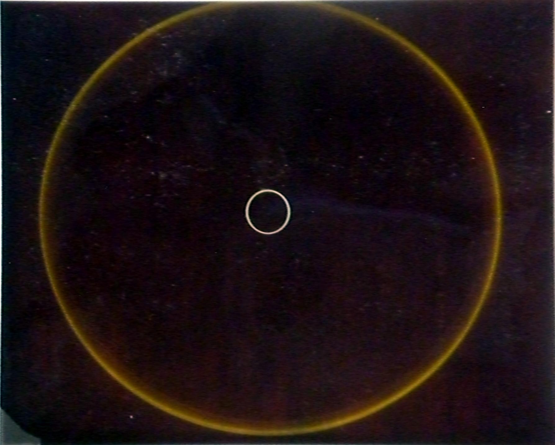
Check the lens.
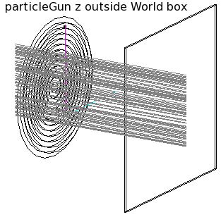
Spray photons at fixed wavelength, x=0, sweep over y.
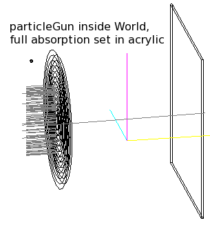
[ Note to make this work, it is not sufficient to just change the particle
type to 'opticalphoton'. These will act as geantinos, as can be seen in the first figure where rays pass straight through the lens, unless
- you assign them a polarization
- the starting coordinate is inside the world box
|
|
(16)
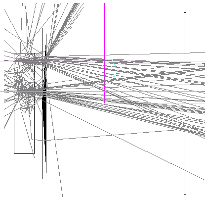
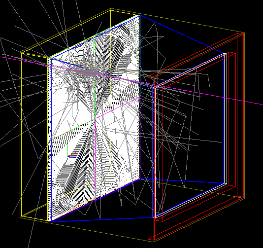
Geant-4 simulations are underway. Shown here are a block
of aerogel, a fresnel lens and a detector plane, and photons produced by
two incident 5 GeV μ+. Notice many photons scattering in
the aerogel block, photons absorbed in the fresnel lens, and Cherenkov cones
converging near the detector plane.
| 
|
(17)
Rings made with this configuration. Shown are photon hits (blue) in the detector
plane, and the track hit (red). Scale is in mm.
More rings:
1,
2,
3,
4,
5.
| 
|
(18)
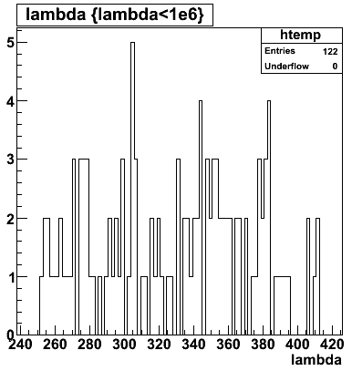
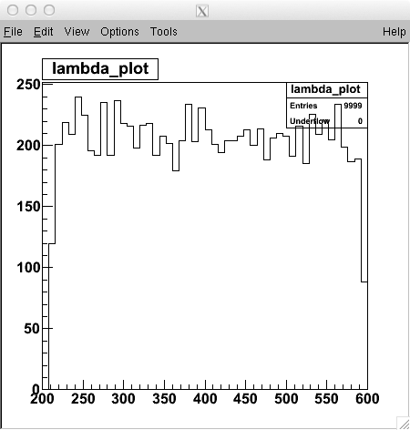
Check the Acrylic transmission spectrum. Make a particleGun that sprays photons
at (x,y)=(0,0), and sweep over wavelengths 200-600 nm.
| 
|
(19)
Number of grooves. In the simulation, each groove in the fresnel lens
is built (in cross section) as
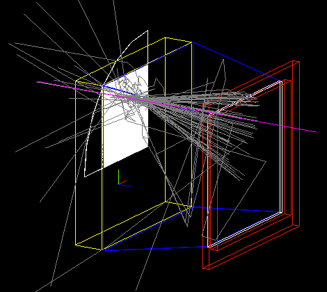
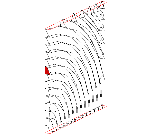
a prism with flat faces. Therefore the focal point will have a spread no
smaller than the width of one groove. On the right, the lens has 13 grooves,
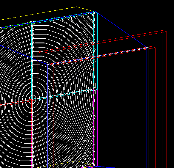
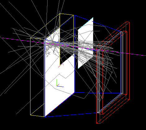
and below, 130 grooves. Focus is improved.

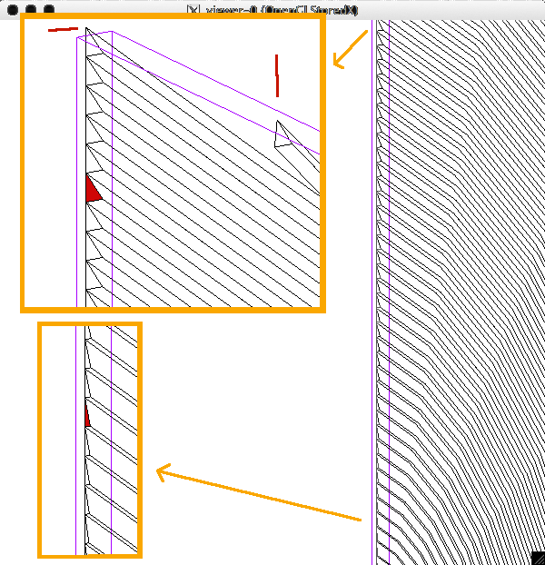
| 
|
(20)
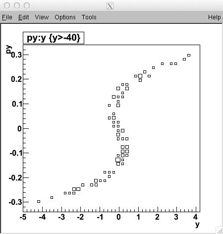
Fix aberrations. The focusing is still bad. This is due mostly
to high-angle rays, and can be fixed by adjusting the asphericity parameters
in the definition of the lens.
Plotted are the the vertical coordinate of incident rays in the focal
plane (y) vs. the angle (py) of the ray. We want these points to line up
at y=0.
Starting parameters:
Curvature: 0.0132/mm
Aspher[1] =  4.2067 e-5/(mm)
      [2] =  9.644 e-10/(mm3)
      [3] = -1.488 e-15/(mm3*mm3)
      [4] = 0
| 
|
(21)
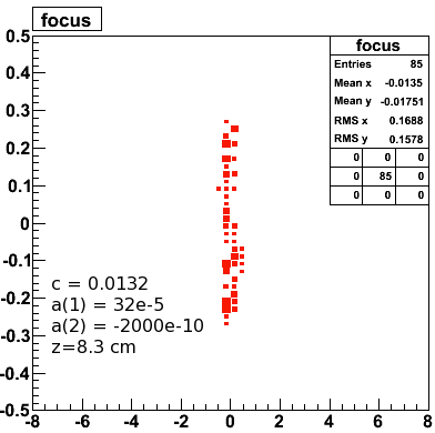
Optimized asphericity.
The aspericity parameters are changed to produce a sharp focus.
Also moved the focal plane a bit.
| 
|
(22)
Non-parallel rays.
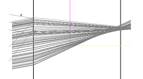
However, none of our Cherenkov photons are parallel to the optical axis. Here,
the photons make a 10° angle, and the focusing is terrible again.
(come back to this later)
| 
|
(23)
Cherenkov cone. A single 1 GeV muon is thrown at (0,0),
making a ring in the
plane that was optimized for parallel incident rays. The ring width
has 0.23mm sigma.

| 
|
(24)
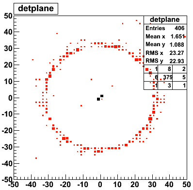
Cherenkov ring. Ten 5 GeV muons are thrown at (0,0), parallel to
the optical axis. The incident muons are shown in black.
| 
|
(25)
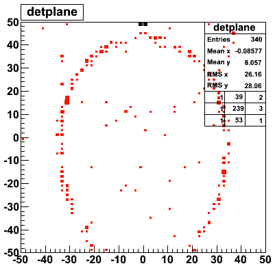
Cherenkov ring. Ten 5 GeV muons is thrown at (0,+5cm), parallel to
the optical axis. The lens tips the cone down, and the intersection of
a cone with the detector plane is an ellipse. The ellipse is not exactly
top/down symmetric because of aberrations.
The pattern recognition can be taught to translate the
distortions into an y,x coordinate of the incident particle.
| 
|
(26)
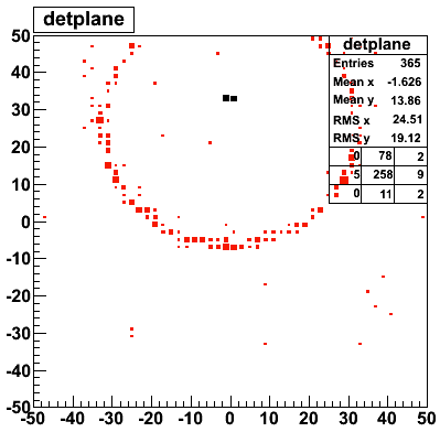
Cherenkov ring. Ten 5 GeV muons is thrown at (0,0cm), but at a
10° angle relative to
the optical axis. Similarly, off-axis tracks can be recognized also.
| 
|
(27)
Smaller Cherenkov ring. By making the focal length of the lens shorter
(14→12.5 cm),
the rings in the imaging plane are smaller. Ten 5 GeV muons are thrown
at (0,0), parallel to
the optical axis. The incident muons are shown in black.
| 
|
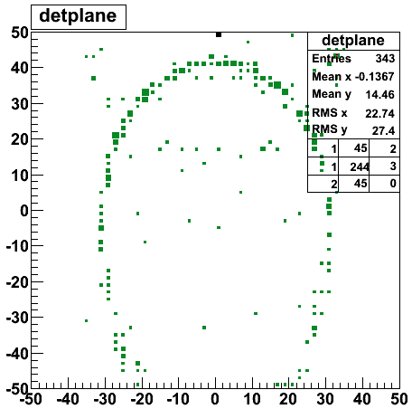
(28)
Smaller Cherenkov ring. The off-center ring is more contained.
Ten 5 GeV muons is thrown at (0,+5cm), parallel to
the optical axis. The aberrations of the lens produce a distorted ring in
the focal plane. The pattern recognition can be taught to translate the
distortions into an y,x coordinate of the incident particle.
| 
|
(29)
Smaller Cherenkov ring. An 8° off-axis track is now fully
contained.
| 
|
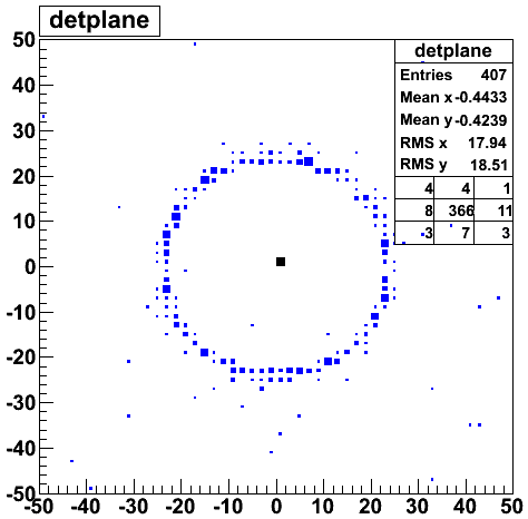
(30)
Smallest Cherenkov ring. By making the focal length of the lens even
shorter (12.5→10.4 cm),
the rings in the imaging plane are smaller. Ten 5 GeV muons are thrown
at (0,0), parallel to
the optical axis. The incident muons are shown in black.
| 
|
(31)
Smallest Cherenkov ring. The off-center ring is more contained.
Ten 5 GeV muons is thrown at (0,+5cm), parallel to
the optical axis. The aberrations of the lens produce a distorted ring in
the focal plane.
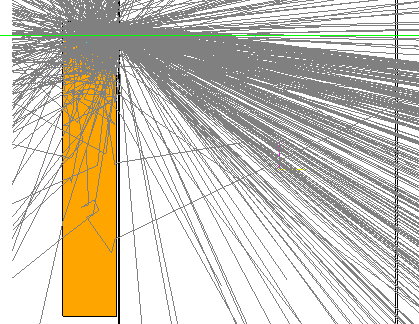
Clearly the lens has trouble with the bottom half of the ellipse. Note
these rays are bent by ≈45°, and the lens becomes very inefficient.
| 
|
(32)
Smallest Cherenkov ring. An 8° off-axis track is now fully
contained. Ten 5 GeV muons is thrown at (0,0cm), but at a
10° angle relative to
the optical axis. Similarly, off-axis tracks can be recognized also.
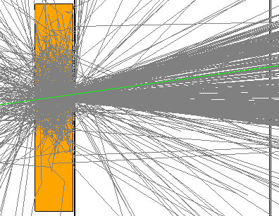
The top of the ring seems to be inefficient. Not sure why.
| 
|
Interim conclusion: As expected, very-low-f-stop lenses are difficult, and an intermediate focal length needs to be used.
|
(33)
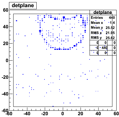
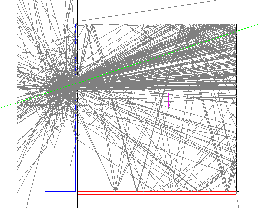
If we have to compromise on the focal length, then sections of some
of the rings of
interest will fall outside the detector plane boundary. If we want to recover
these sectors, we can have the walls of the module be flat mirrors.
| 
|
(34)
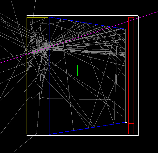
If we want to stack these modules, then everything needs to be contained
in a box no bigger than the aerogel size. The readout plane (white) presumably
needs some support and connections on the perimeter (red), and therefore
is smaller than the box. Therefore we tilt the mirrors slightly.
| 
|
(35)
So far, the lens is still modeled as a full circle. It needs to be trimmed
into a square. Simple Geant4 boolean volume operations do not
appear to do the trick so far ...
| 
|
(36)
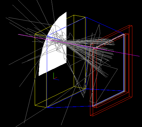
The reason is that the lens is built as a parametrized volume.
Trimming the mother volume does nothing to the grooves.
Each
groove in the lens traces out a narrow arc (in the original above a full
circle) with a triangular cross section (each groove is actually a PCON).
For each arc, the PCON properties can be
calculated separately. So we make up the lens out of 4 sectors. Starting at
the center, the grooves are quarter-circles, which is fine until you come
to the edge of the aerogel. But further out they should subtend smaller and
smaller angles.
| 
|
(37)
This is done here. The volume holding the grooves is still a quarter circle.
| 
|
(38)
Here the full lens is made up of 4 sectors like this, where the mother
volumes are now individual square boxes, since parametrized volumes
must each be contained in their own mother volume. Here they have different
colors, visible on the edge of the 4 sectors (green, red, magenta, light blue).
The last quarter is lifted out a bit for clarity.
| 
|
(39)
Next detail: the figure shows a cross section of the fresnel lens (I got this
lens from Geant4 example /advanced/airshower). The
enlargements show that the grooves near the center are flatter than those
near the top, as they should be. As a result, near the center the fresnel lens
approaches zero thickness. In real fresnel lenses that I have, the apexes
(apices?) of the prisms stay in one plane, instead of going down. Also, at
the bottom of every groove the acrylic in the model has zero thickness -
clearly not like real fresnel lenses.
Fix this next.
| 
|
(40)
Here is a side view of the new lens. The parametrization was changed so that
the grooves were not made from
CONS (cone section), which only allowed
triangular cross section, to
POLYCONE,
which allowed volumes with arbitrary
shape and rotational symmetry.
Here you can see that the cross section of each groove is now a trapezoid,
and that
the tip of each trapezoid touches the red containing box. I have also defined
a minimum thickness so that the deepest groove does not cut all the way
through to the flat side of the lens.
Source code here
|
Here is the current module, with fresnel 100 grooves, such that the
groove width is about 0.8 mm. Also shown now is the containing box
in green, with nothing sticking out.
|
|
| 
|