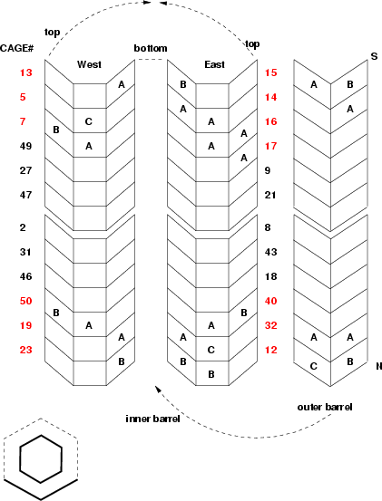
| On the left is shown the year-3 configuration of the MVD.
The inner barrel is fully occupied, and the bottom rows of the outer barrel
are populated. The cages toward the center are unmodified, and cages in red
are changed from last year. The A, B, (C, D) indicate the rating of
the MCM that services the silicon in this position, as far as this is assigned
at the moment.
- Fewer than 10/256 dead channels
- Fewer than 32/256 dead channels
- 1 block (32/256) dead channels
- 2 blocks (64/256) dead channels
In addition, both end caps are fully populated with pad detectors.
<- ps
|

|
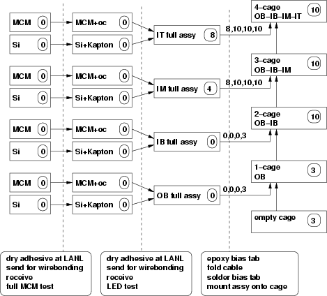
Shown is a map of the current state of the remaining silicon assembly.
From left to
right, the steps involve: MCM is bonded to an output cable, sent off to
Pace for wirebonding. Silicon is bonded to Kapton cable and sent to Pace.
These 2 subassemblies are joined and sent to Pace. Upon return, they are
tested with an LED, a bias tab is epoxied to the back of the silicon,
then the Kapton cable is pre-folded, and the bias tab is soldered onto
the back of the Kapton cable. Finally, the full assemblies
are glued onto the C-cage, in order OB, IB, IM, IT (outer bottom, inner
bottom, inner middle, inner top).
The total number of cages in the MVD is 24. 11 were completed last year, and
3 more have been finished this year. Thus 10 are still under
construction. The numbers in ovals indicate how
many (sub-) assemblies still need work.
<- ps
Pictures of the procedure are
here.
|
|

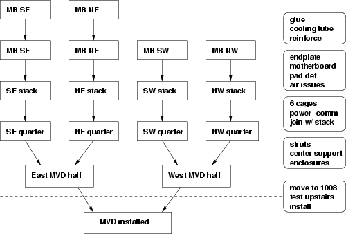
| The final assembly procedure.
Pictures of the (dis-)assembly are
here.
<- ps
| |


