The results presented in the following sections were obtained using the most recent version of PISA available to us, namely version 2.03/00 obtained from BNL in May, 1995. Both the UA1 and RV_JPSI event generators were used. Three sets of output were obtained for each event generator. In one case the lead shield and neutron shield were installed; in the second case they were omitted. In the third case both the shields and the nosecone were omitted. In addition, a set of runs was made for 500 events. Due to the long running time for ua1 events this was done only for the ``shields out, nosecone in'' case. A partial listing of the gffgo.dat file used for the ``shields in'' case is as follows:
CUTS  .002  .005  .002  .005  .005 .005 .005 1.e+4 1.e+4 .002 4.e-7
GEOP 'ENDC' 'CENT' 'PIPE' 'NOSE' 'NTSH' 'PBSH'  !Passive elements
VER  'FULL' 'P_ID' 'NONE' 'NONE' 0.0  0.0       ! MVD but no hits
MUN  'FULL' 'ETOT' 'FULL' 'NCAL' 0.0 0.0 0.0 'STCK' 'NNEU'  !Muon ID
MUW  'FULL' 'ETOT' 'FULL' 'WCAL' 'NONE' 0.0 0.0 'STCK'      !Side
MUM  'FULL' 'ETOT' 'FULL' 'MCAL' 0.0 0.0 0.0 'STCK' 'NNEU'  !Muon trk
Note that the ``NNEU'' parameter suppresses storage of neutral hits. The corresponding file for the ``shields out'' case is identical except for the line
GEOP 'ENDC' 'CENT' 'PIPE' 'NOSE'and for the ``nosecone out''
GEOP 'ENDC' 'CENT' 'PIPE'A partial listing of the ua1event.par file used for the runs is:
  ntotal =  9000,  <-- 9000 particles emitted.  This is approximately
                       equivalent to a ``single'' HIJET event.
  include = 8, 9, 18*0,  <-- Only pi+ and pi- emitted
  the_minc =    3.0,  <-- Min theta = 3 degrees
  the_maxc =   60.0,  <-- Max theta = 60 degrees.  This is probably
                          larger than necessary.
For the RV_JPSI generator angle and momentum filters were used to
guarantee that all particles were emitted into the muon arm with
sufficient momentum to penetrate beyond plane 3 of the muon identifier
for the ``shields in'' cases. The angle range was  to
to
 and the minimum momentum was 2 GeV/c.
The version of PISORP used was downloaded from the ``Soren'' Silicon Graphics computer at U. T. on August 17. This is the version used by Ken Read and Saskia Mioduszewski in preparing for the Albuquerque meeting that took place on August 14-15. We have modified it to store the histograms that are shown in Figs. 2- 5. These figures show the number of events for which 1, 2, 3,..,8 roads are found such that each road produces hits in (at least) planes 1, 2, and 3 of the muon identifier. A partial listing of the mun_digi.par file used with PISORP is:
 $nml_readout1_init
   seg_type = 2, 2, 2, 2, 2, 2,
   min_coord1 = -655.32, -655.32, -655.32, -655.32, -655.32, -655.32,
   delta_coord1 = 8.0, 8.0, 8.0, 8.0, 8.0, 8.0,
   min_coord2 = -516.8, -516.8, -516.8, -516.8, -516.8, -516.8,
   delta_coord2 = 8.0, 8.0, 8.0, 8.0, 8.0, 8.0,
   eff_neut = 0.000, 0.000, 0.000, 0.000, 0.000, 0.000,
   eff_gam = 0.0, 0.0, 0.0, 0.0, 0.0, 0.0,
   eff_chrg = 1.00, 1.00, 1.00, 1.00, 1.00, 1.00,
 $end
These parameters are the same as used for Ken Read's report at the Albuquerque meeting. In particular, the segmentation_type 2, 2,... entry corresponds to detector strips of 8 cm width with the hodoscopic ambiguities turned ``on''. Replacing this with segmentation_type 1, 1,... turns the hodoscopic ambiguities ``off''.
The road finding scheme used to obtain these results starts in plane 1 of
the muon identifier. The beginning of a road is signified by hits in both
a vertically and a horizontally mounted proportional tube. The intersection
of these tubes defines the x, y coordinates of the beginning of the road.
The tubes in plane
two whose intersection is closest to the same  ,
, coordinates, measured with respect to the vertex, as the hits in plane 1
are then checked for hits. If no pair of hits is
found, then adjacent tubes on either
side are checked for hits. When a pair of hits is found,
the algorithm continues to project forward to check plane three for hits in
exactly the same fashion as for plane 2.
coordinates, measured with respect to the vertex, as the hits in plane 1
are then checked for hits. If no pair of hits is
found, then adjacent tubes on either
side are checked for hits. When a pair of hits is found,
the algorithm continues to project forward to check plane three for hits in
exactly the same fashion as for plane 2.
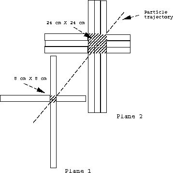
Figure 1: Schematic of the trigger road finding algorithm used in this
study. The third plane
of the muon identifier is searched for hits
over a 24 cm X 24 cm area
exactly as indicated here for the second plane.
This search area in plane 2 thus includes 9 square regions, each 8 cm X 8 cm in area. This scheme is indicated in Fig. 1.
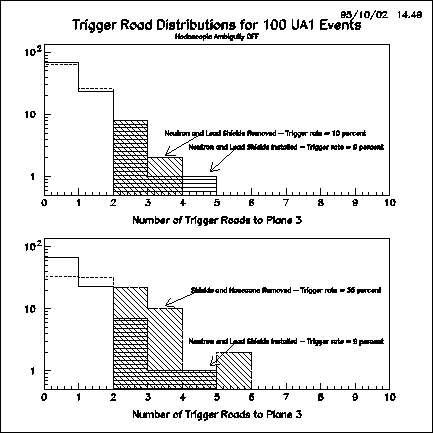
Figure 2: Distribution of trigger roads for 100 UA1 Events.
The histograms at
the top show superimposed the number of trigger roads
for the cases where the lead and neutron shields are installed and
the number of roads produced when these shields are omitted.
The histograms at the bottom show superimposed the number of
roads produced when both shields and the nosecone are installed and the case
where all three items are omitted. For all cases the hodoscopic ambiguities
in the strip detectors are turned ``off''. The shaded areas represent the
numbers of roads ( ) that produce a trigger.