Mounting ROCs on the cooling plate


Also see: Tie-down buttons,
and leveling gap-pad material
(1) Have the cooling plate checked for flatness
(2) Mount the 4 fiber transceivers on the ROC

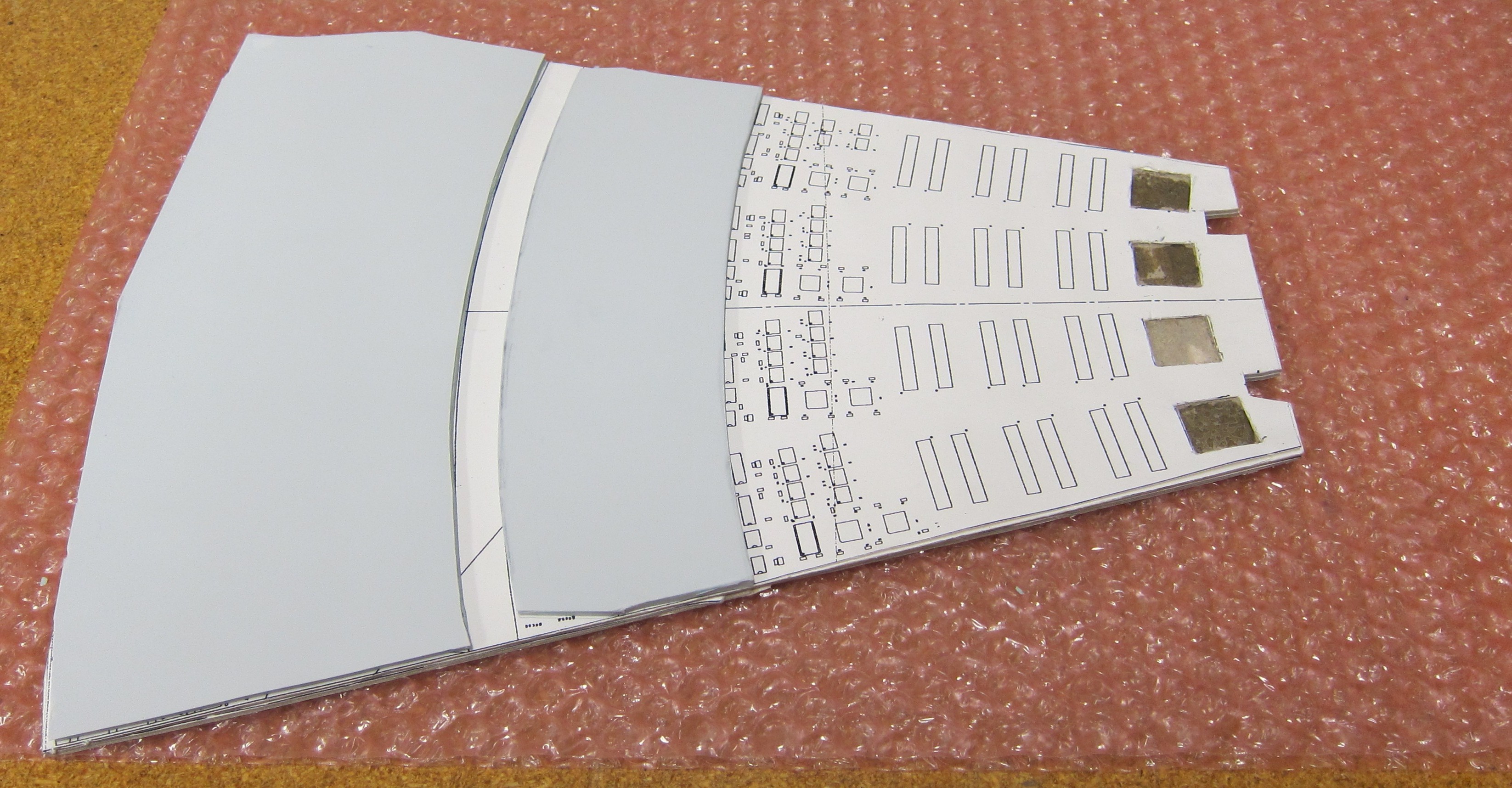
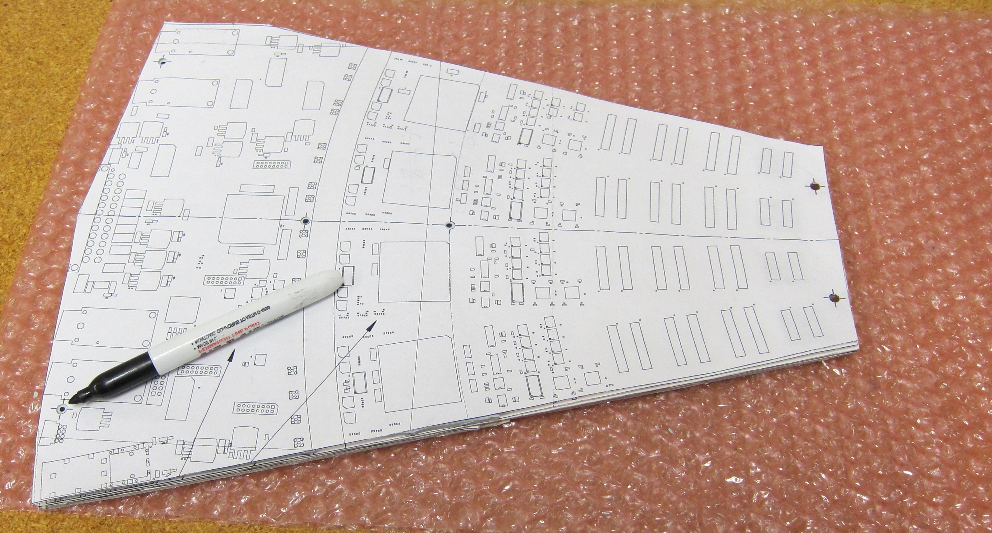
(3) On a cardboard ROC mockup, lay out the gap-pad material (gpm), preferably with the white side up. →

Addition: we decided to also add gpm at the narrow end of the board, where the extension cable connectors are.
(4) Using the paper ROC, mark the 6 screw holes on the gpm, and cut them out. The holes should be big enough for the spacer washers →
(5) Peel off backing
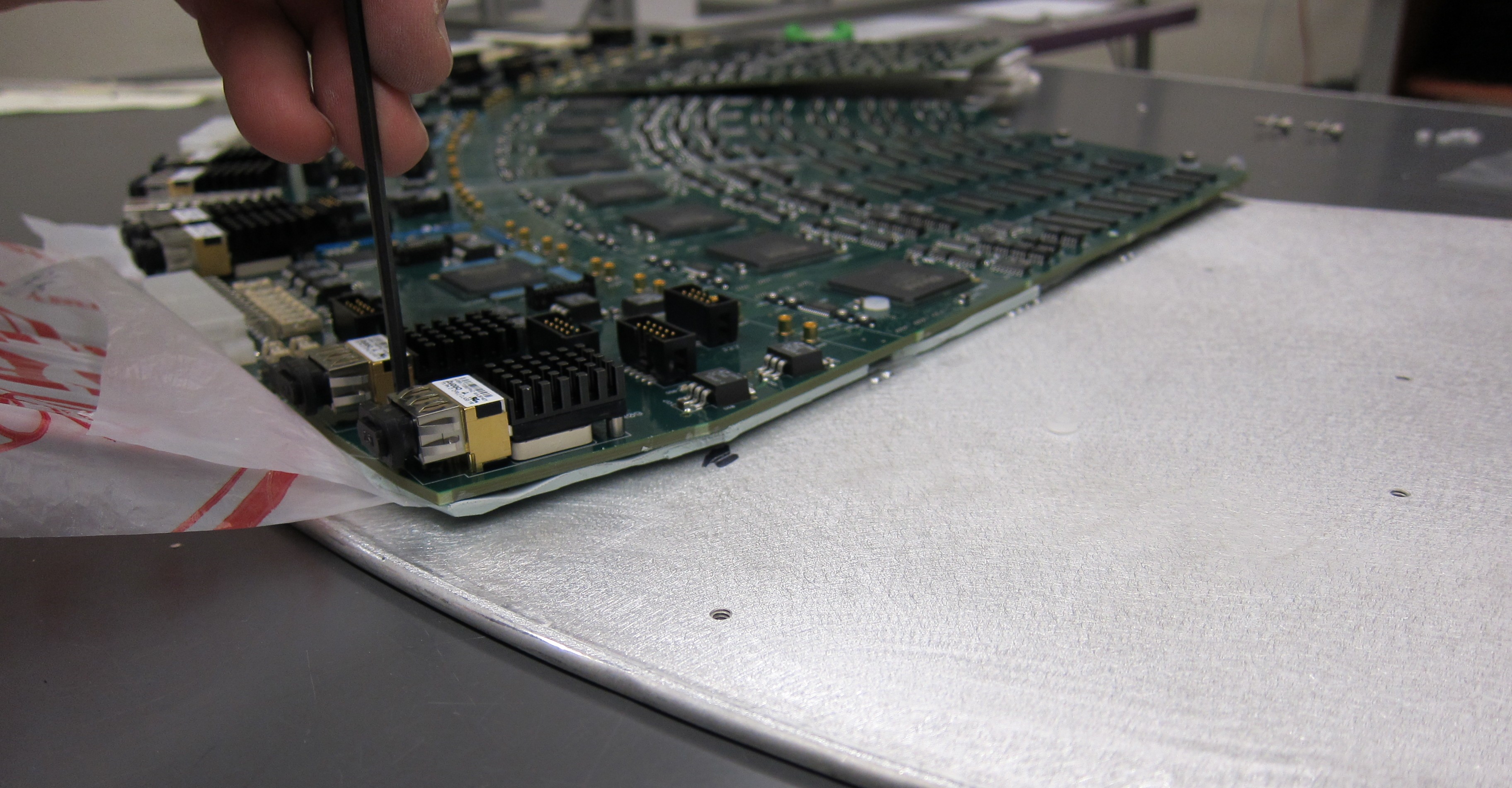
(6) Position ROC, and press down →
(7) Flip the sandwich over, and remove cardboard ROC →
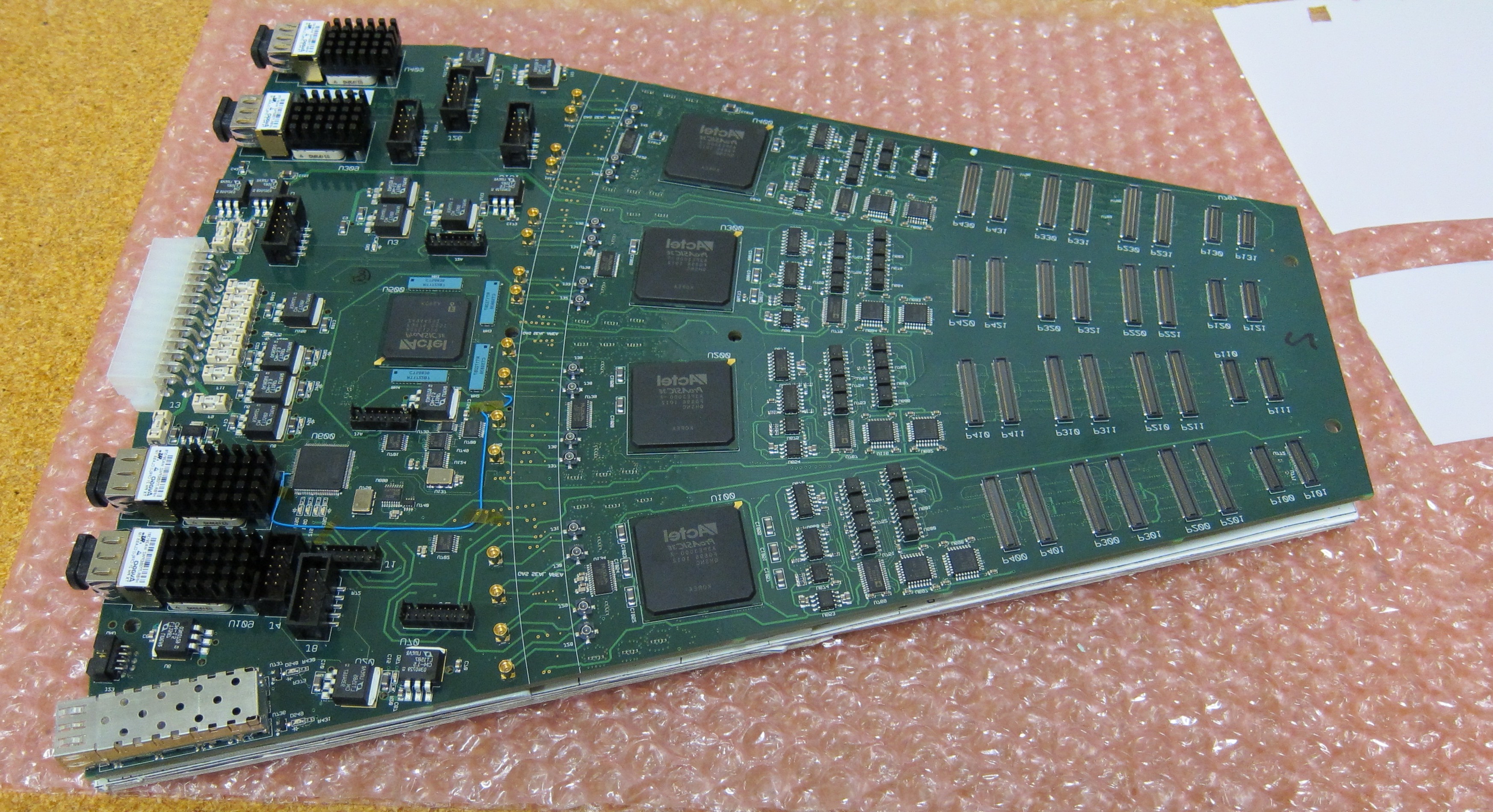
(8) Peel the backing off, press gpm down over the backside components
(9) Place in leveling jig and shave bumps.

Addition: also shave bumps on the narrow-end gpm.


See leveling gap-pad material
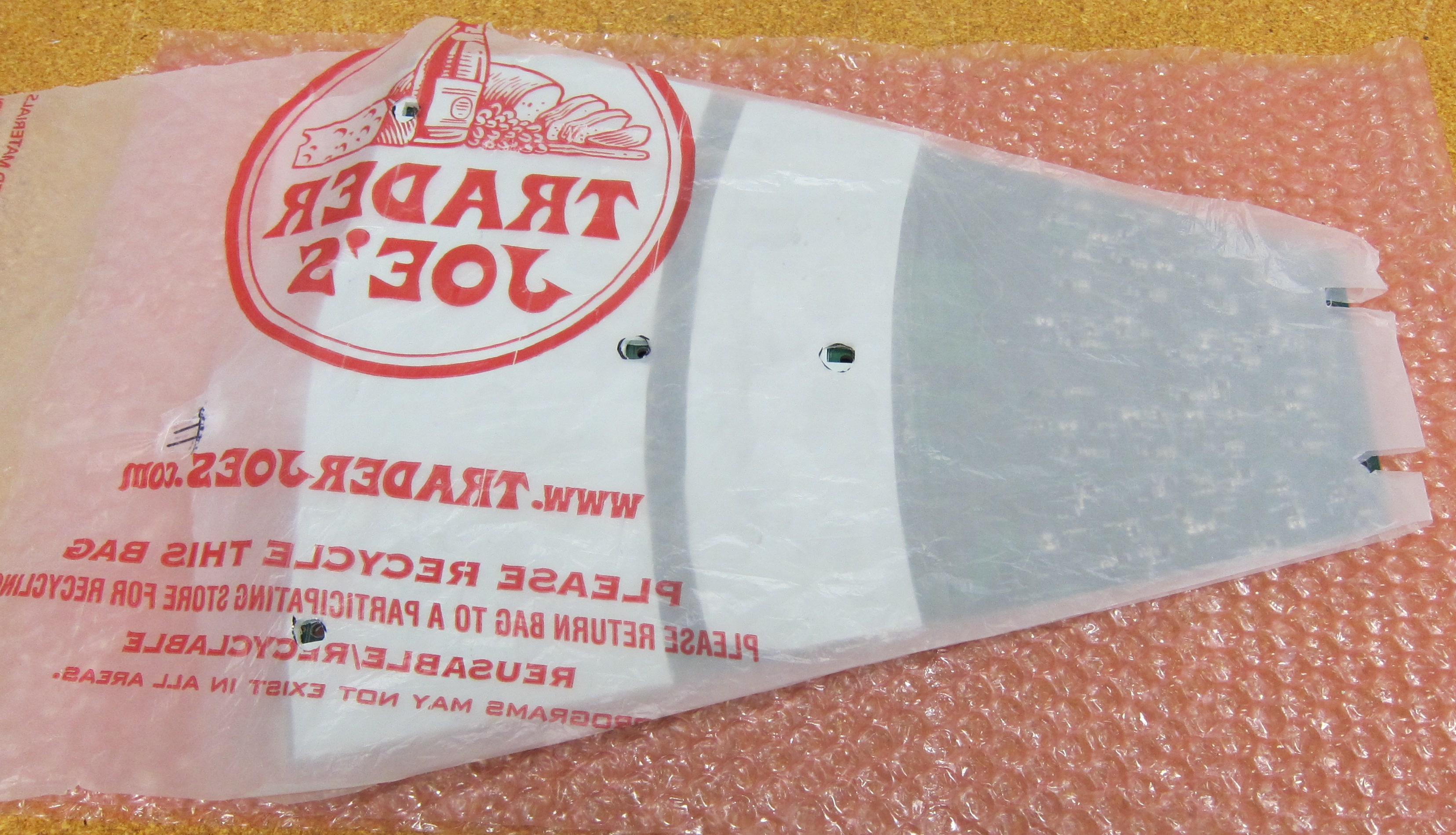
(10) Remove from the leveling jig onto bubble wrap, replace backing and feel for flatness
(11) Place the spacer washers in the gpm holes, check them for alignment with the ROC screw holes
(12) Put the double plastic on, with the long side up, and remove backing from the gpm


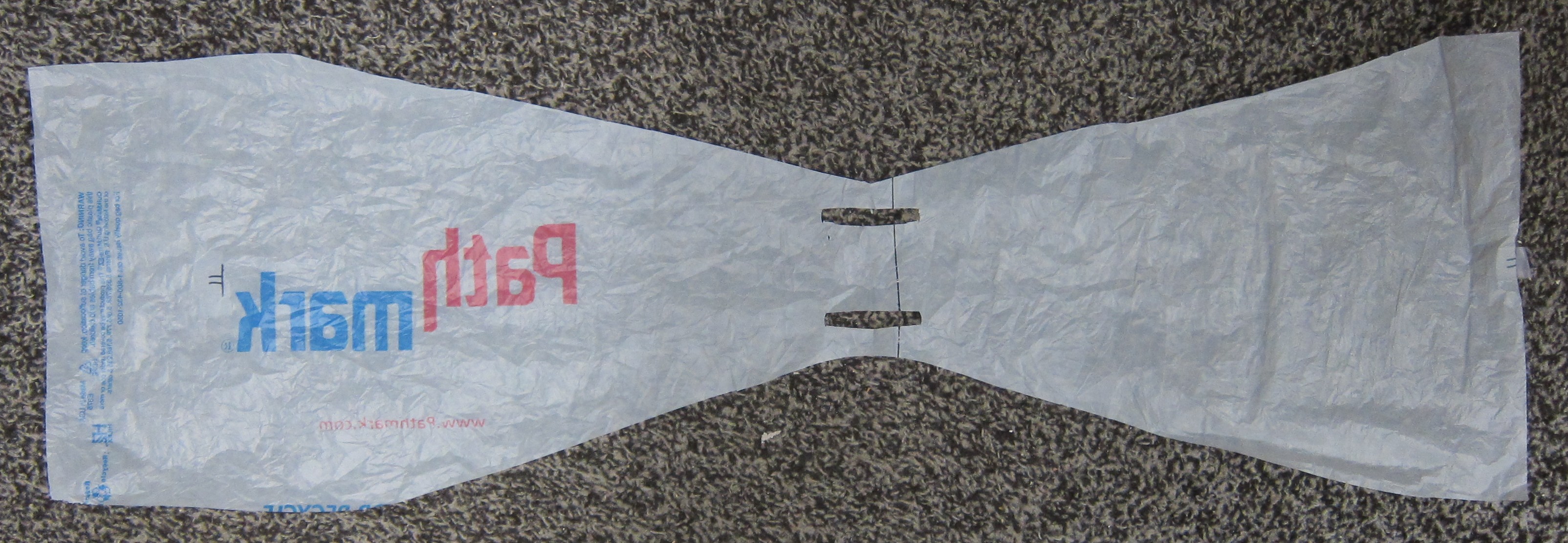
Note the fold in the plastic hangs ove the narrow end of the board →
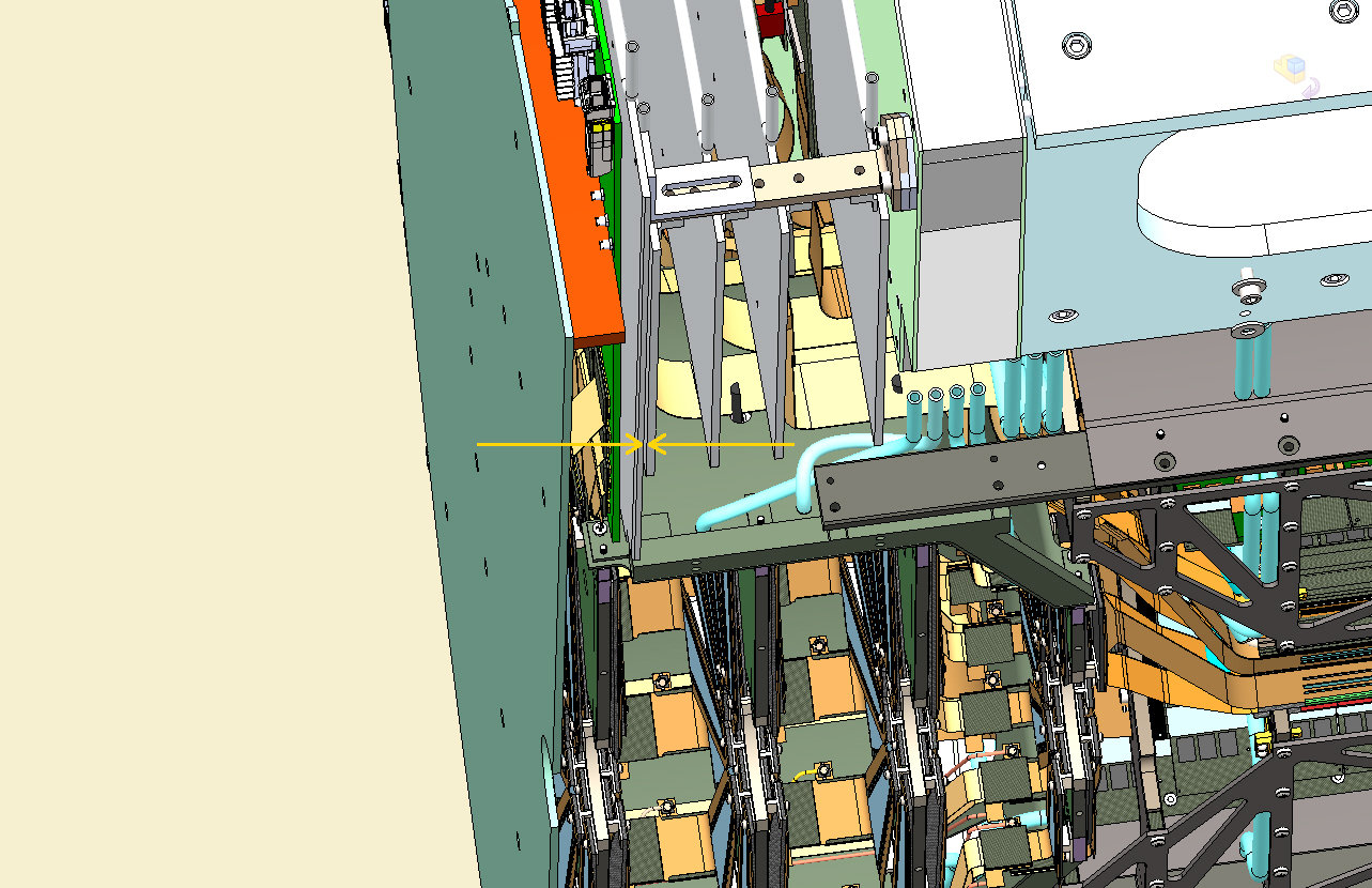
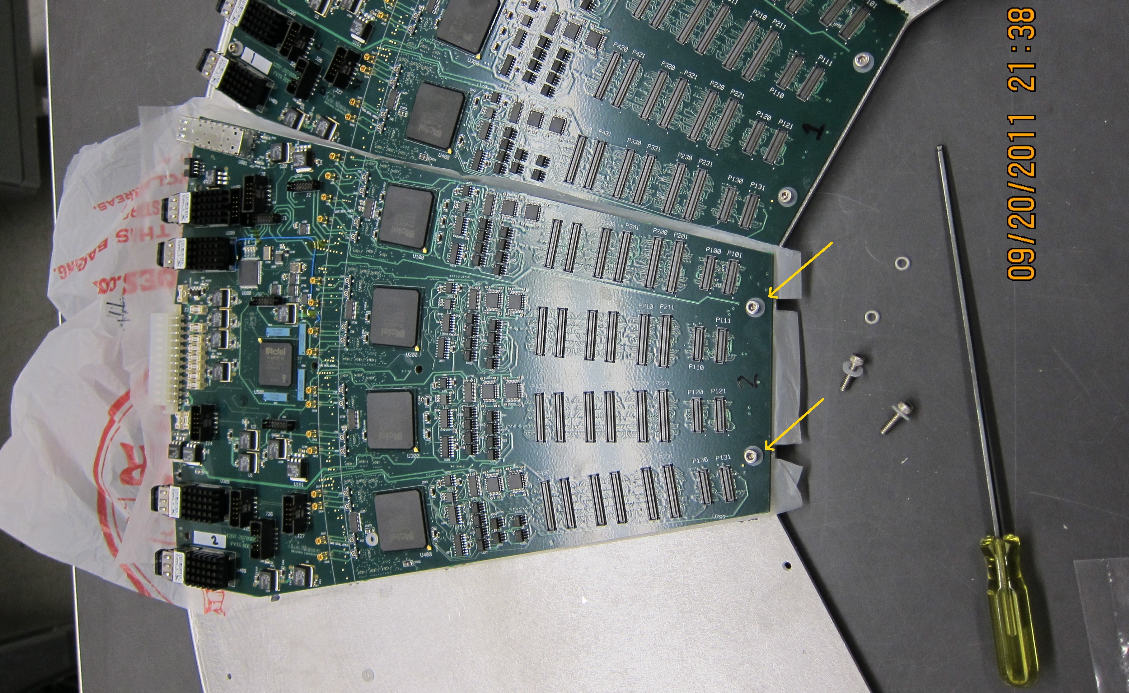
(13) Add cardboard roc, and flip over
(14) Place this sandwich on cooling plate
(15) Put in the two 6-32 screws on the narrow end. These are 2 nylon screws, no washers, so that they are as low-profile as possible. The extension cables will pass over these screws.
(16) Tip up the wide end, hold the plastic on the narrow end, and pull out the cardboard ROC →
(17) Align the ROC by checking the position of the screw holes using the 6-32 allan driver, and slowly pull out the plastic →
(18) Put in the remaining 4 screws: the two along the ROC center line are special standoff screws, mounted with plastic washers. These will hold up the outside enclosure cover plate.

Finally the 2 screws on the outside perimeter. These can be regular 6-32 screws, with plastic washers.

(19) In the final installation we only have 1.27 mm space behind our cooling plate. Therefore the innermost 4 scews (2 nylon, 2 spacers) should not protrude more than that from the back surface. Check the back of the cooling plate. The outermost 2 don't matter.

Hubert Van Hecke
Last modified: Thu Oct 6 09:42:19 MDT 2011