tray (3)

previous page


(1)
Layer A tray:
layera_1.stl, layera_2.stl, layera_3.stl,
layera_4.stl, layera_5.stl, layera_6.stl,
layera_7.stl, layera_8.stl, layera_9.stl,

Shown is layer A top cover, full size, 3x3 plates with hold-downs, on 1/8" carbon fiber honeycomb panel (2 more sections to go). Holes on the perimeter are defined by the prints (10 cm intervals)

(8)
Top cover A-side. Holes on the outgoing fiber side at 4cm intervals. These maybe need standoffs

The backside (layer B) needs to register exactly with this A-side, so I'll use the through-going threads for this. I redid the Layer B tray to add a flange that fits over the threads. This ensures back-front alignment.

layerb_1.stl, layerb_2.stl, layerb_3.stl, layerb_4.stl, layerb_5.stl, layerb_6.stl, layerb_7.stl, layerb_8.stl, layerb_9.stl

14 Jun 22

(2)
Arielle designed new SiPM-side conncetors, where the groups of 16 1mm fibers come together to fit the 4x4mm SiPM. 16 (x2) fibers get glued into the glue block, and then pushed into the connector.

connector_v2ap.stl
glue_block.stl
(3)
We saw connectors at the FNAL fiber lab, picture below. These would be perfect for us. They are 35×8×4 mm. The holder supports this connector and its counterpart, and are held in place with the cover (and 2 6-32 screws). The 15° angle allows for them to be placed closer together.


fnal18_holder.stl
fnal18_holdertop.stl

(4)
If I pack the holders (brown) together, there is a conflict between the screws on the outgoing connector (green) and the yellow cover, so I modified the cover. Also, the holders step up 1mm (0,1,1,2,2,3mm) which creates additional clear space on top.

fnal18_holder2_0mm.stl
fnal18_holder2_1mm.stl
fnal18_holder2_2mm.stl
fnal18_holder2_3mm.stl
fnal18_holdertop2.stl

conn_drill_plate.dxf
top_drill_plate.dxf
fnal18_in.stl
fna l18_out.stl
(5)
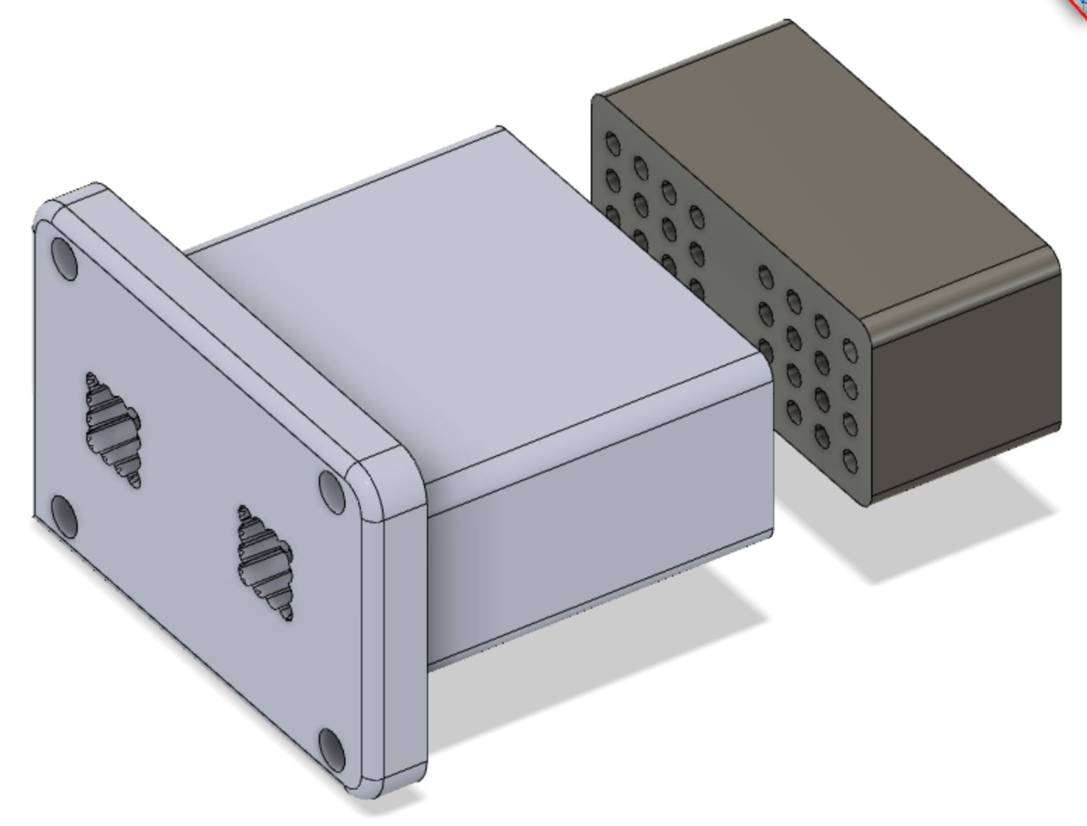
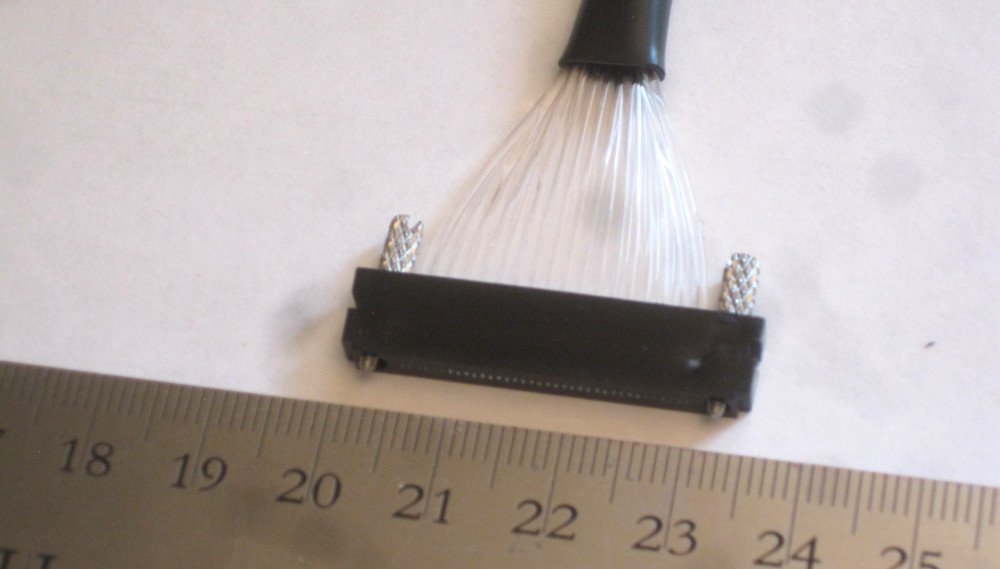
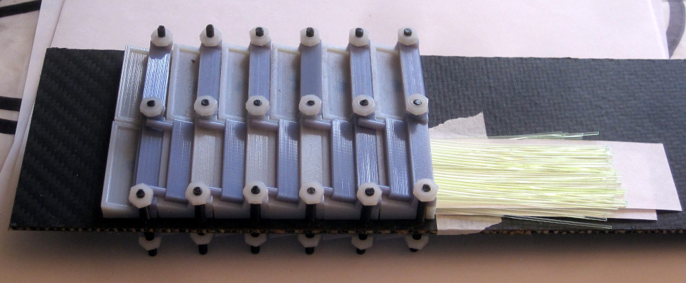
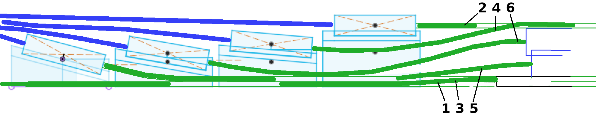
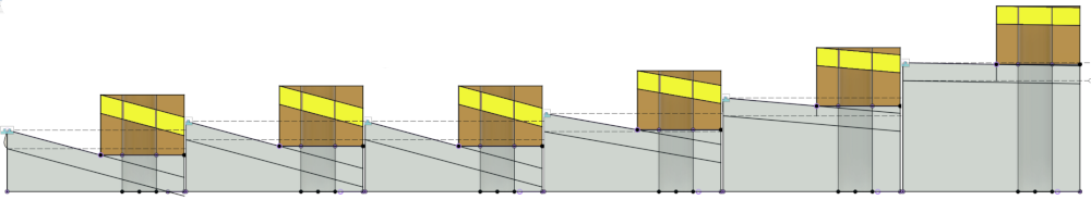
Using mockups of the incoming wls connectors and the outgoing clear fiber connectors, this is as compact an arrangement as possible (20mm space from connector to connector). incoming wls fibers pass (from the right) under the connectors, which have 0,1,1,2,2,3 mm clearance underneath.

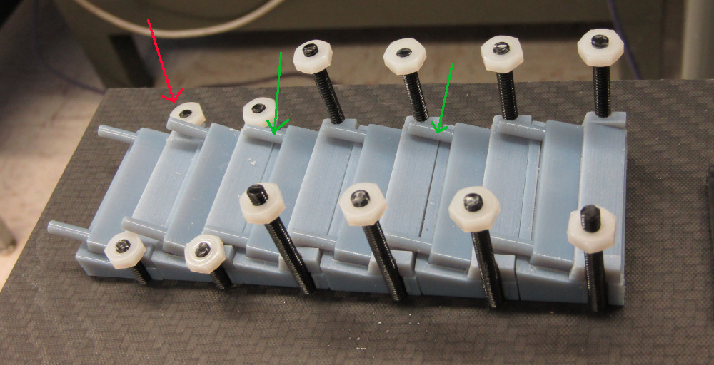
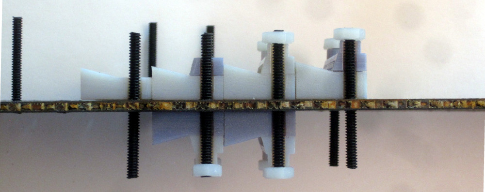
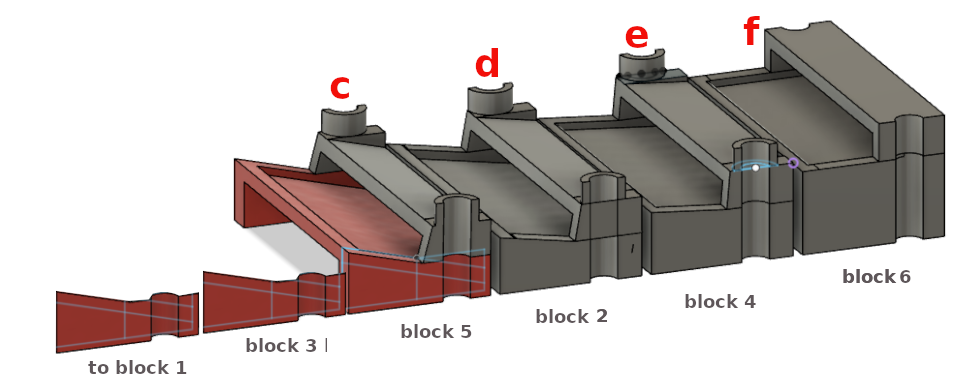
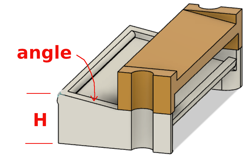
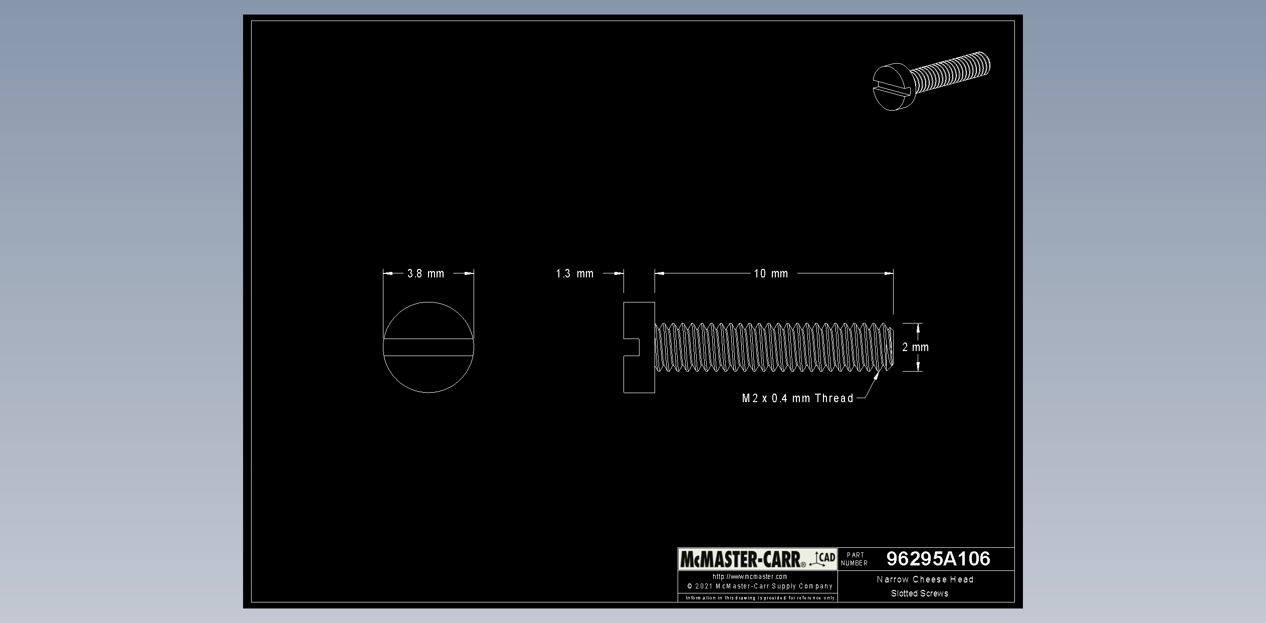
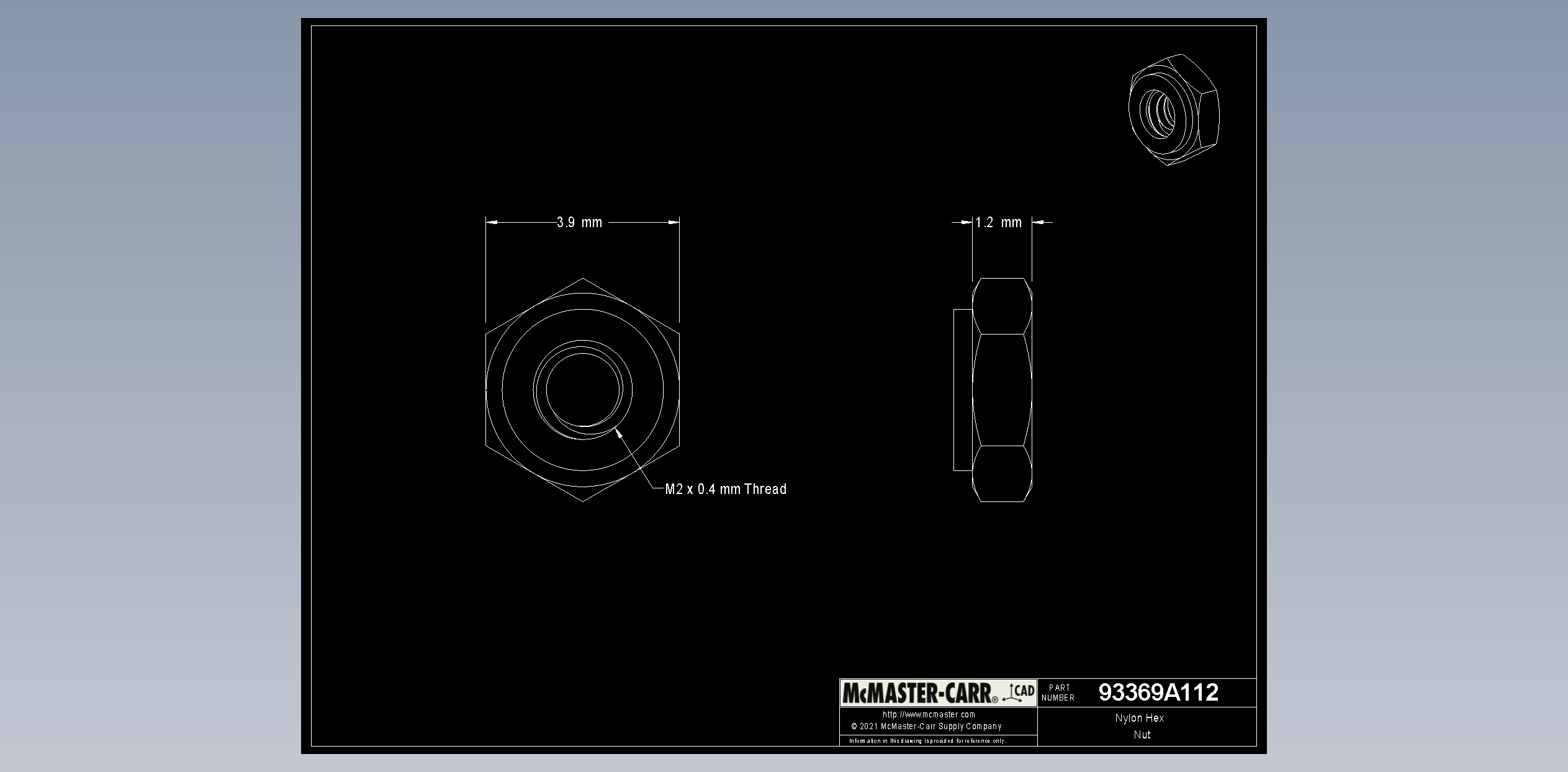
There are 2 conflicts on top: the nuts get in the way of the outgoing connector screws (red arrow), and the equal-height holders (1,1 and 2,2) lead to interference (green). 
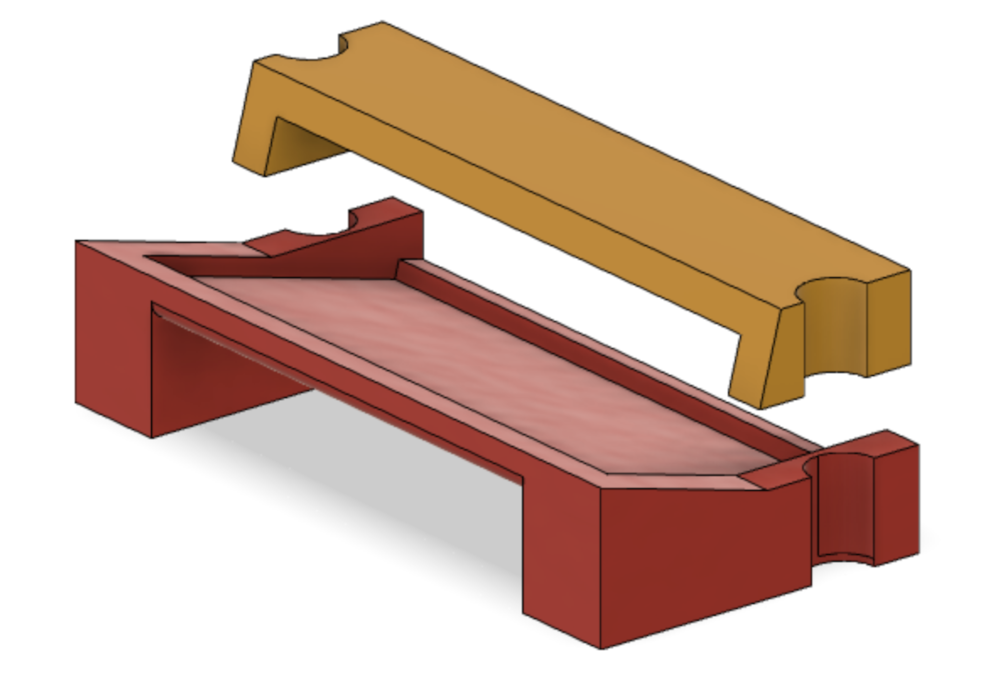
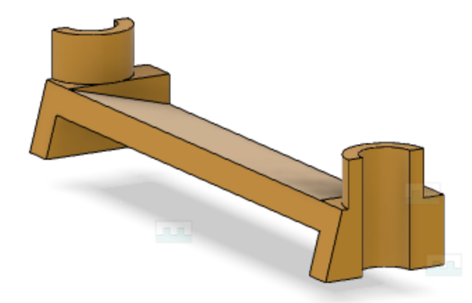
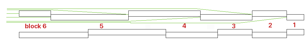
So use 0, 1, 1.5, 2, 2.5, 3mm clearances, and add 'standoffs' on the cover.

fnal18_holder2_1.5mm.stl
fnal18_holdertop3.stl

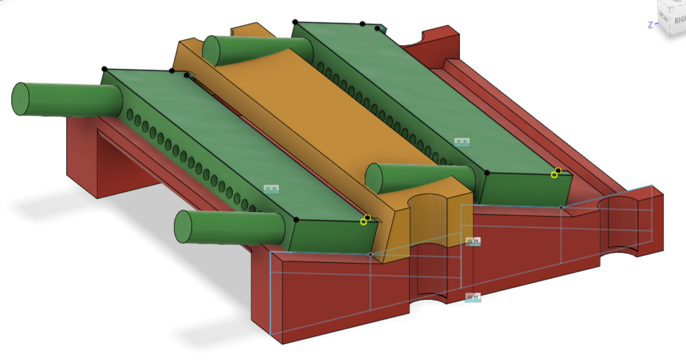
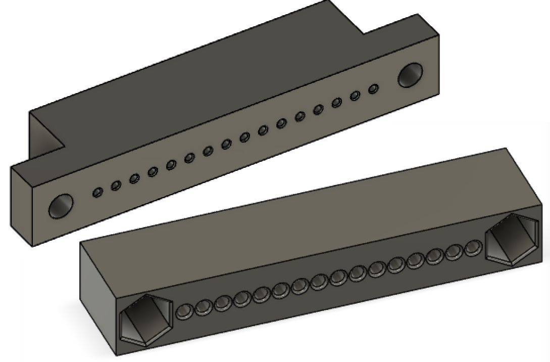
Another problem is that the width of the opening underneath needs to be >=32mm, to accomodate 2×16 1mm fibers per layer. Reprinted all:
fnal18_holder3_00.stl,
fnal18_holder3_10.stl,
fnal18_holder3_15.stl,
fnal18_holder3_20.stl,
fnal18_holder3_25.stl,
fnal18_holder3_30.stl


With these holders, and mockup connectors, this picture shows the fibers coming out on the right in 3 layers.


This sideview shows connectors mirrored on the opposite side

(6)
Problem with the connectors above:
The incoming fibers (from the right) for scintillator blocks 1,3,5 come along the bottom surface, so these connectors and holders are fine. But the fibers from block 2,4,6 are routed along the top of the blocks, so the fibers would need to zigzag from the top to the bottom surface, which would require some distance. We want therefore the connector for block 6 is lifted up such that the fibers enter straight, and 2 and 4 are also raised.
(7)
So it looks like with reasonable bending, we can place the connectors as close as ~2cm to the end of the tray.

fnal18_holder_d.stl
fnal18_holder_e.stl
fnal18_holder_f.stl

fnal18_holder_c.step
fnal18_holder_d.step
fnal18_holder_e.step
fnal18_holder_f.step

top4.stl
top5.stl
top6.stl


fnal18_top_e1.step
fnal18_top_d1.step
fnal18_top_d1.step
fnal18_top_f1.step

connectors:
fnal18_in.step
fnal18_out.step


So the full set of 6 is:
fnal18_holder3_00.stl    going to block 1
fnal18_holder3_10.stl    going to block 3
fnal18_holder3_15.stl    going to block 5
fnal18_holder_d.stl    going to block 6
fnal18_holder_e.stl    going to block 4
fnal18_holder_f.stl    going to block 2
Rosie is making fiber bundles much like ours:

ppt presentation


OK, we're not getting connectors with thumbscrews from Fermilab or any other place, so we brew our own. Also, there are now objections to any metal components.

Connectors using nylon M2 nuts and screws

M2 screws at McMaster 96295A702, specs
M2 nuts at McMaster 93800A300, specs

conn_m2_in.stl
conn_m2_out.stl

The dimensions of the M2 nut means the connectors have to be thicker (8mm), which means the holders and tops need to be redesigned.

Using these conncetors, I redesigned the holders and holder covers, using 2 parameters. In Fusion look for lhcb->newnew_connectors.
    H(mm) angle    holder stl        top stl
---------------------------------------------
 A   6.86   15 holder_par_a.stl top_par_a.stl
 B   7.86   15 holder_par_b.stl top_par_b.stl
 C   7.86   15 holder_par_c.stl top_par_c.stl
 D   8.21   10 holder_par_d.stl top_par_d.stl
 E  10.46    5 holder_par_e.stl top_par_e.stl
 F  14.38    0 holder_par_f.stl top_par_f.stl


Hubert van Hecke
Last update July 2023