|
(17)
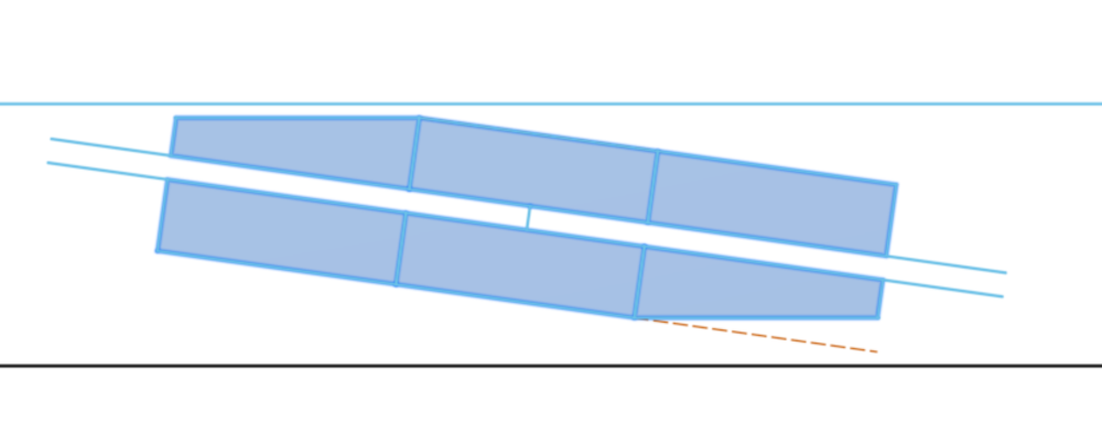
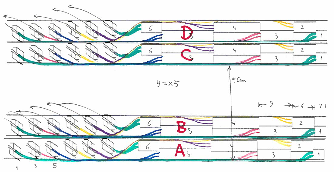
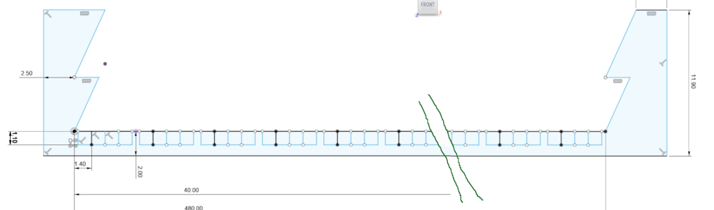
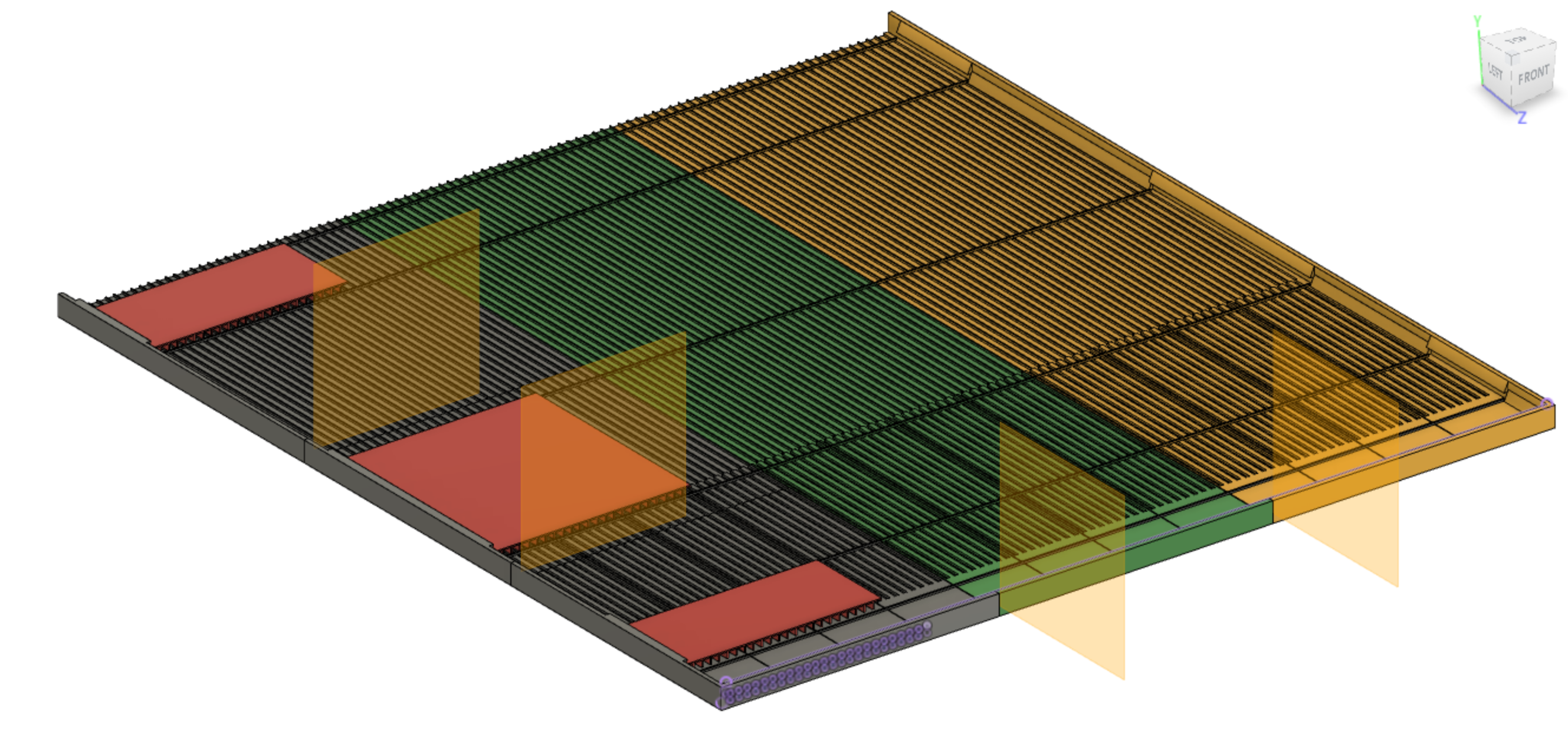
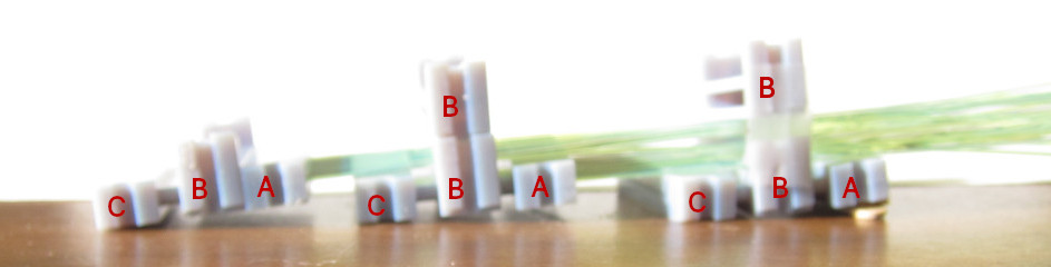
The layers are paired (AB, CD) and the pairs are spaced 5cm apart.
Even though the connectors and fibers now fit inside of 12mm, I cannot
get my fingers in between layers A and B to connect output fibers
(same for C,D).
Note: the y-scale is stretched by ×5
| 
|
|
(18)
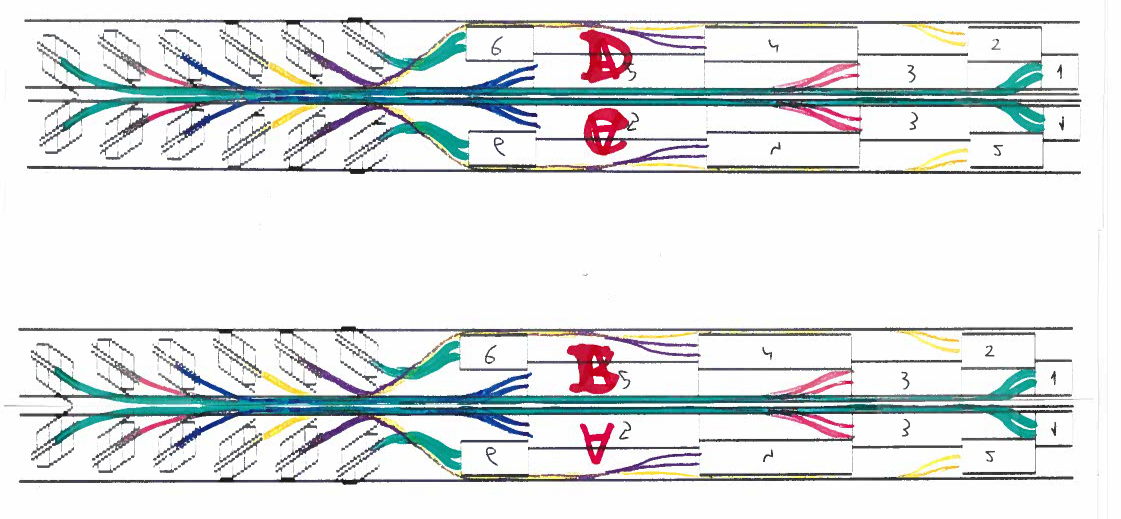
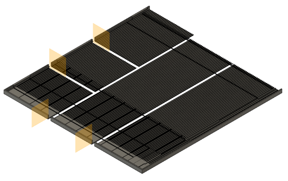
But if I flip A and C, maybe there is finger space to connect outgoing fibers to layers B and C, but likely not.
So during installation, one would mount AB first, and connect outgoing fibers on the two sides, next mount CD in a temporary position such that there is enough space to connect the outgoing fibers to surfaces C and D, and finally move CD into the final position close to AB.
|
|
|
|
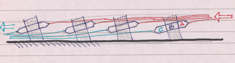
(19)
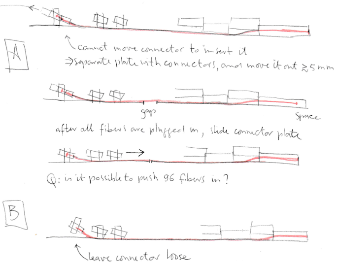
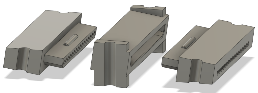
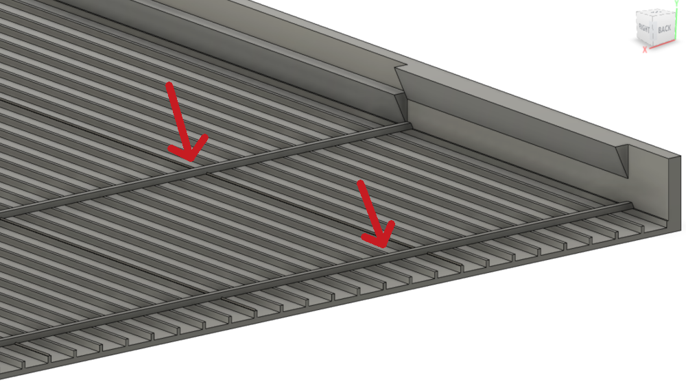
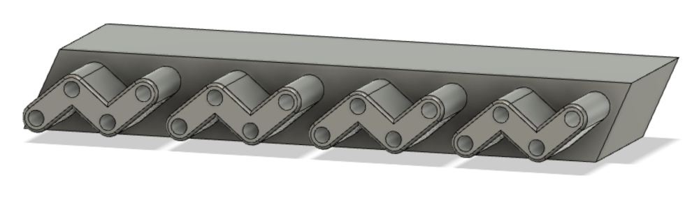
Back one step: How to connect wls fibers to the tilted joiners? In
the top drawing, you see the 1mm wls fiber needs to go from the far end
of the scintillstor bar into the connector which inserts to the center
of the joiner, which needs to be mounted to the board. The fibers are
stiff, and come in groups of 16, so I can't'
back off the connector in order to insert it into the joiner.
[A]
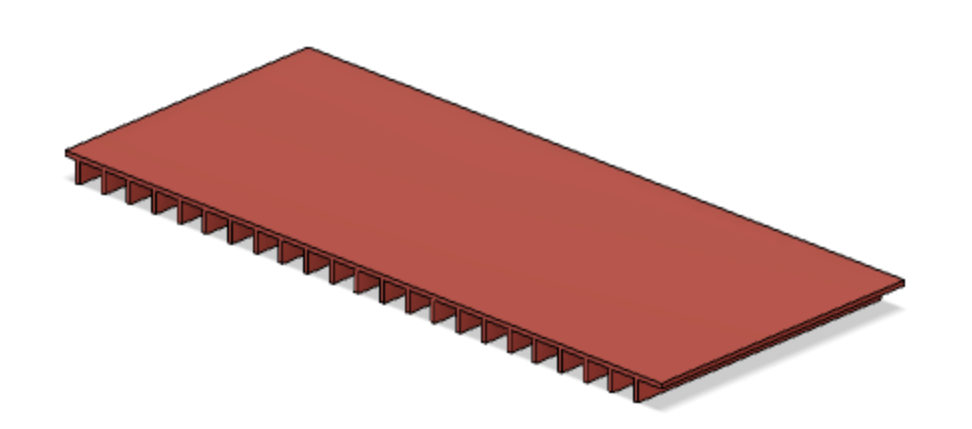
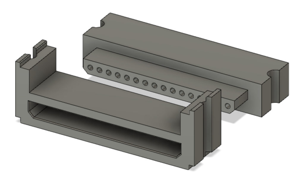
If I split the support board, and separate the parts so that I can
connect the fibers, they get pulled out several mm. Then I have to
slide them back together. But there are 6×16
fibers, and I can probably not slide all of them in at the same time.
[B]
So I leave the joiners loose until the fibers are inserted, and mount them
onto the board later.
| 
|
|
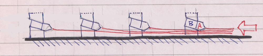
(20)
| 
|
|
(21)
| 
|
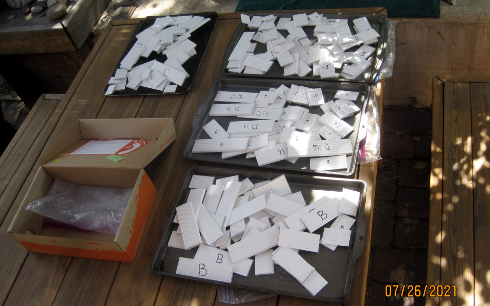
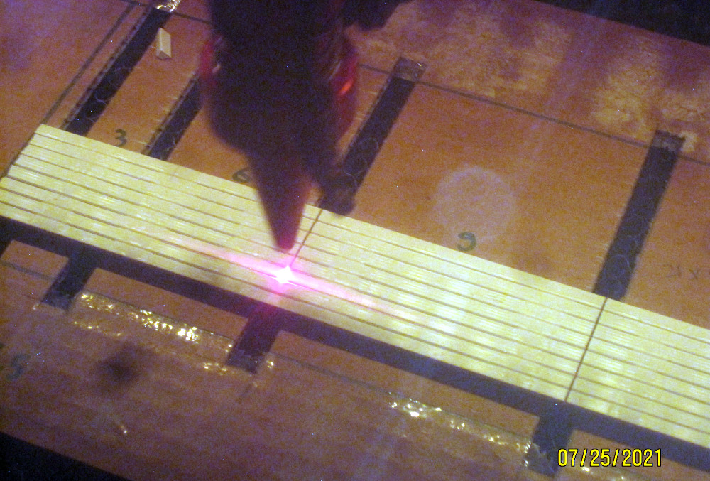
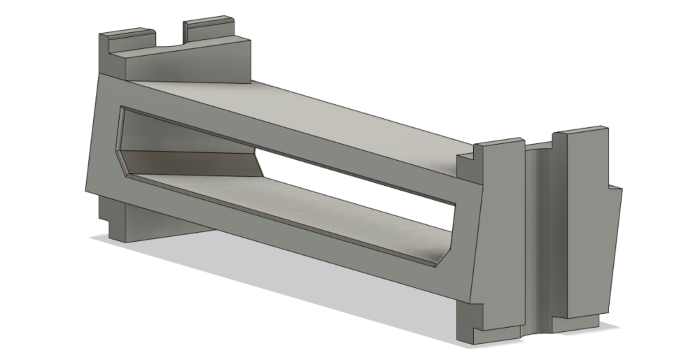
(22)
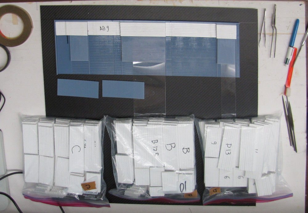
Start test assembly:
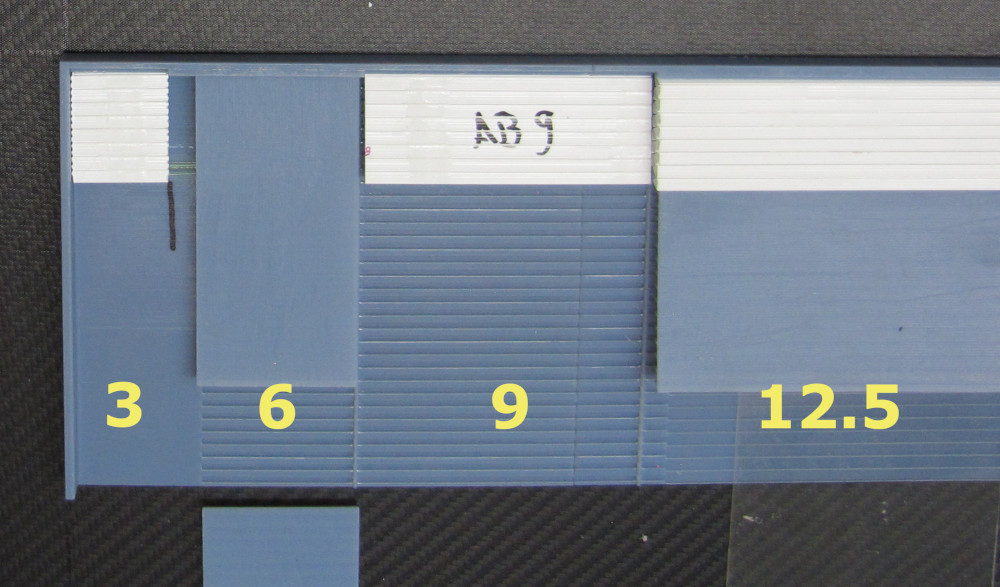
- cut 16 fibers to length
(see 13 here)
- epoxy fibers into connector
- print new polishing blocks
- polish the ends
(see 14, 15 here)
polisher
| 
|
|
(24)
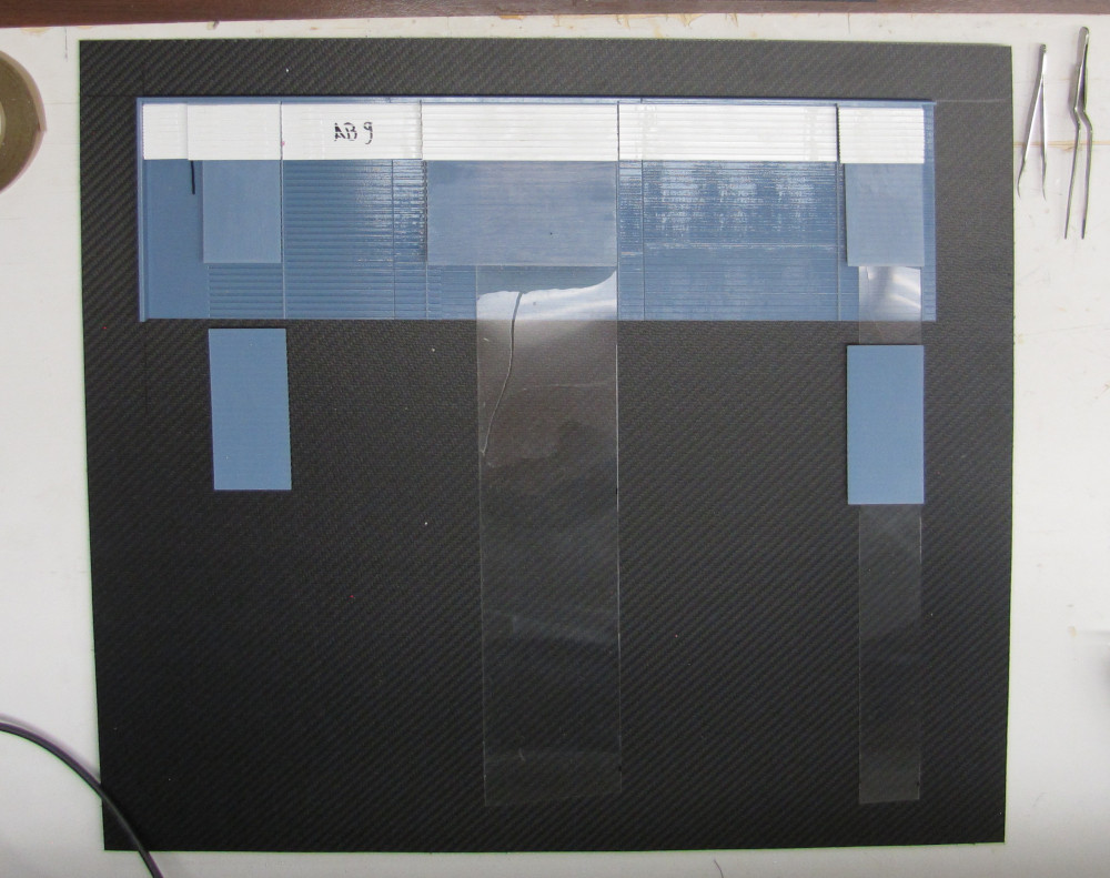
First block:
remove the upstream connectors (this works only because the nylon screws bend).
| 
|
|
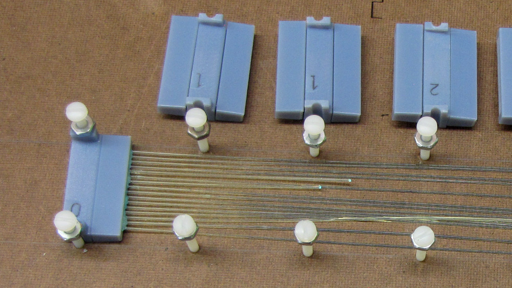
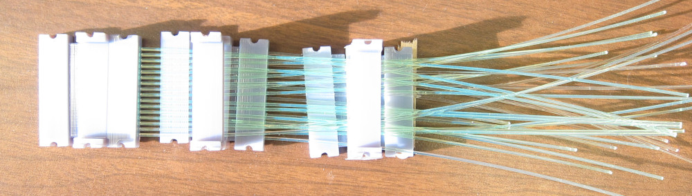
(25)
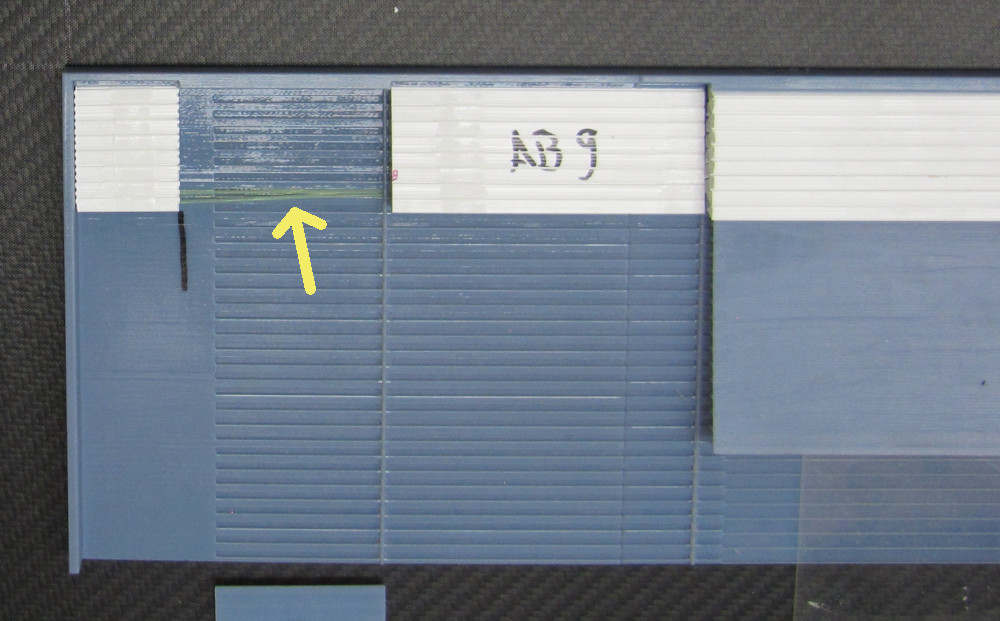
You have to pass the fibers (in order) underneath the bridges. This is tedious.
In the process I discovered that 2 of the 16 fibers were 1.1mm, and the other
14 were 8.8-9.2mm diameter. The thicker fibers will not pass, and I had to
cut them off.
| 
|
|
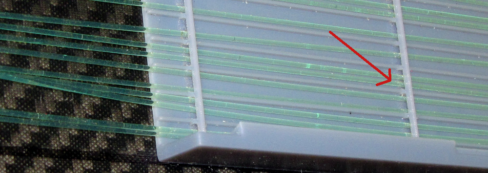
(26)
The connector is inserted into the joiner first, and then
screwed down.
Note the 2 cut fibers.
| 
|
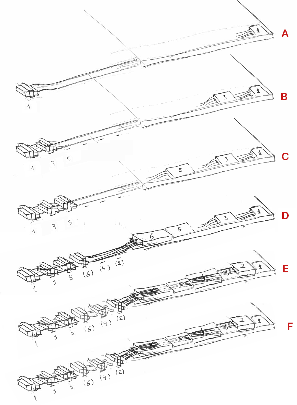
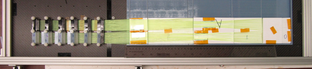
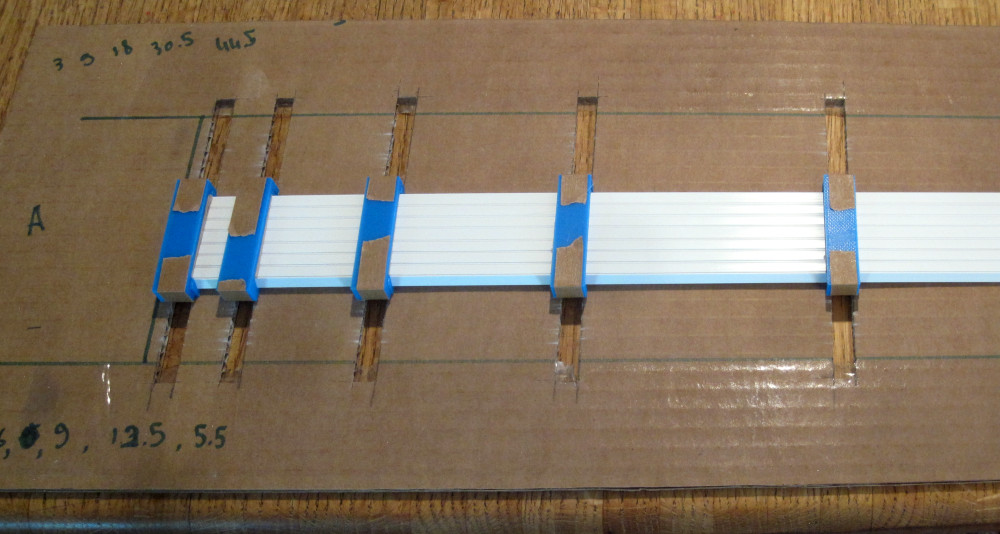
(27)
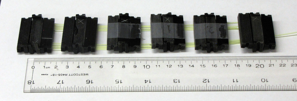
This is how the assembly of one 16-fiber row of blocks goes:
A: 16 fibers for block 1 get routed under
the bridges in the base plate and inserted into block 1. Screw down
connector 1.
B: Fibers for block 3 get routed and inserted
in block 3, connector 3 screwed down, over the fibers from 1.
C: Same for block 5. over the fibers from
1 and 3.
D:Place block 6. When fiting, put connector
joiners 4 and 2 in place.
E: Place block 4. Fibers pass over the top of
block 6.
F: Place block 2. Fibers go over 6 and 4.
| 
|
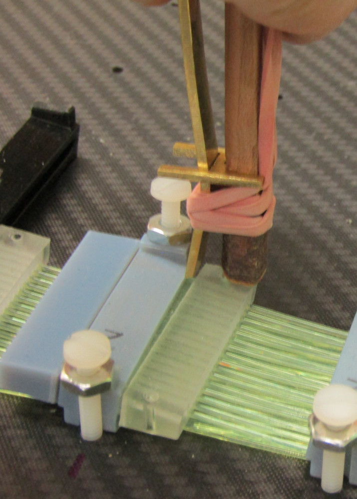
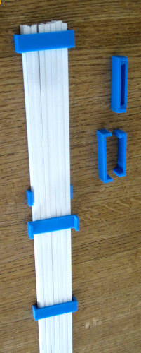
(28)
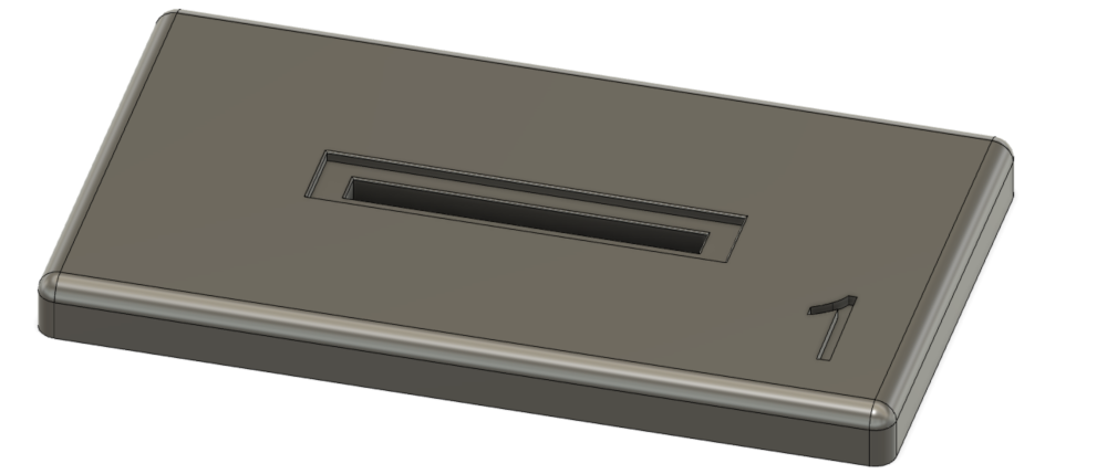
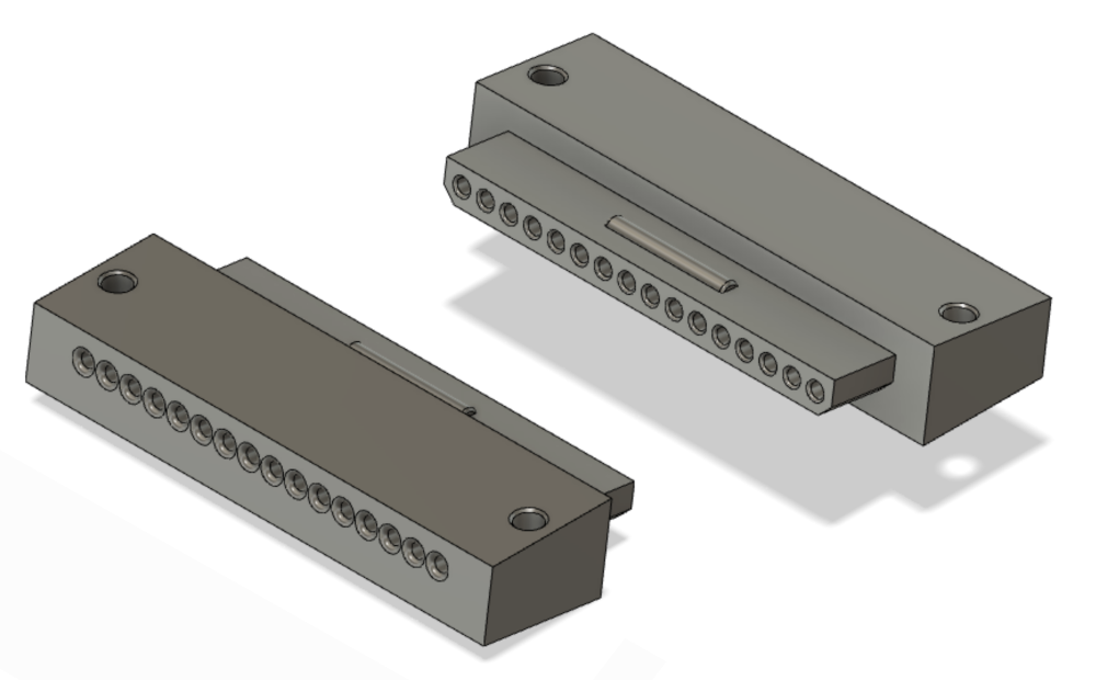
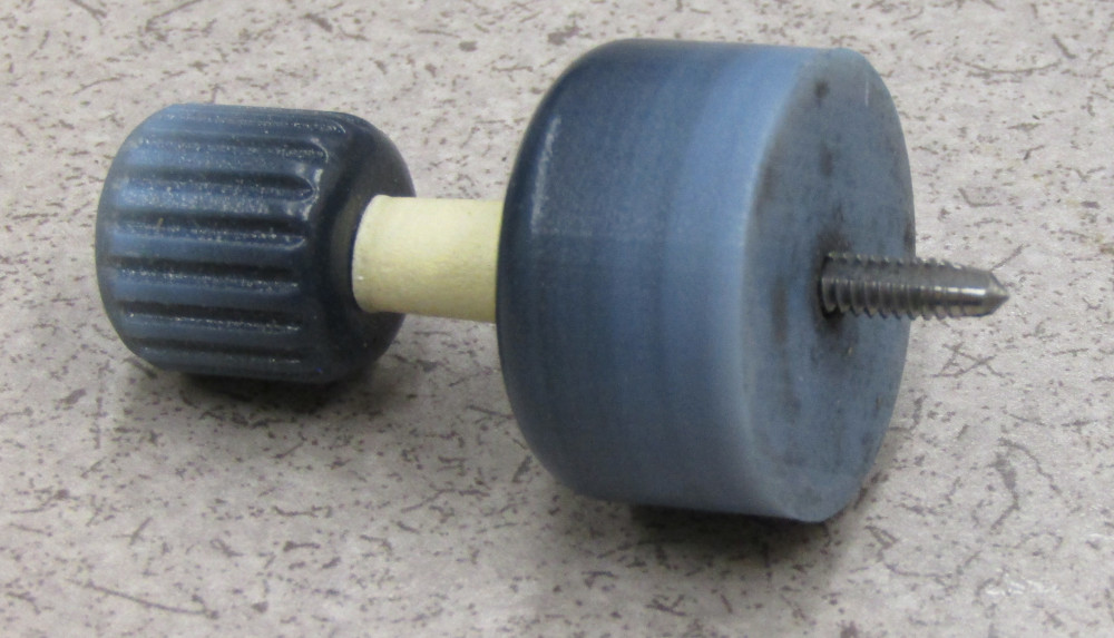
Once the connectors snap in place, they are hard to loosen. I added a pair of holes, and made a spreader tool to facilitate easy loosening of the connectors.
connector tapered input with holes
connector tapered output with holes
| 
|
(29)
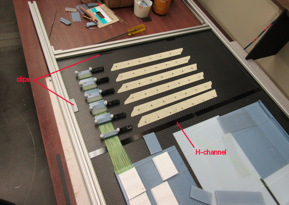
I made a 80/20 frame, with clips to hold the 1/8" carbon fiber boards. I also printed H-channels to join the boards.
H-channel panel joiner
80/20 clip
6-32 tap cap. The connector joiners are screwed down on
a 4×4cm grid of holes tapped in the carbon.
6-32 tap guide
| 
|
(30)
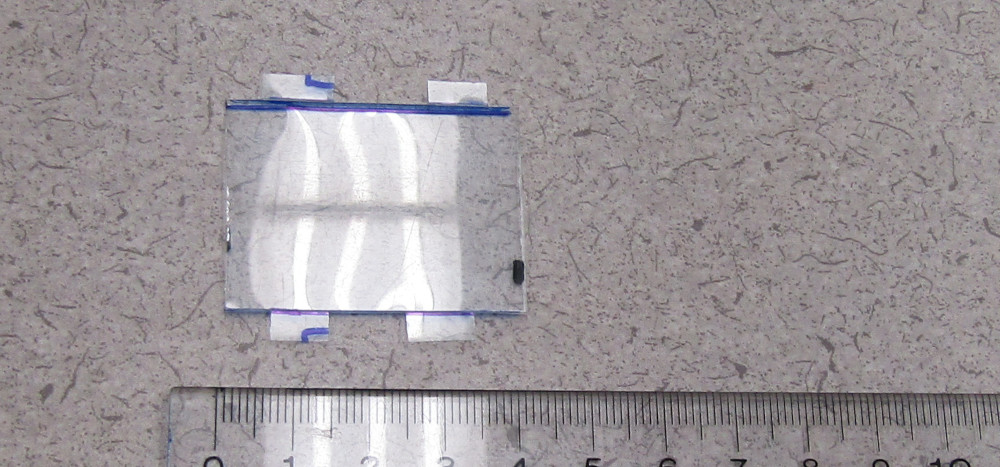
2 rows of layer A finished. Fibers that pass over blocks 4 and 6 are
held with mylar 1mm-high brackets.
| 
|
(31)
The first third of the top cover of layer A. Various nubs hold down the blocks, slipping
in between the fibers. The flange will be drilled to hold it down
with 6-32 screws.
layeratop_left_bot.stl
layeratop_left_mid.stl
layeratop_left_top.stl
layeratop_mid_bot.stl
layeratop_mid_mid.stl
layeratop_mid_top.stl
layeratop_right_bot.stl
layeratop_right_mid.stl
layeratop_right_top.stl
| 
|
|
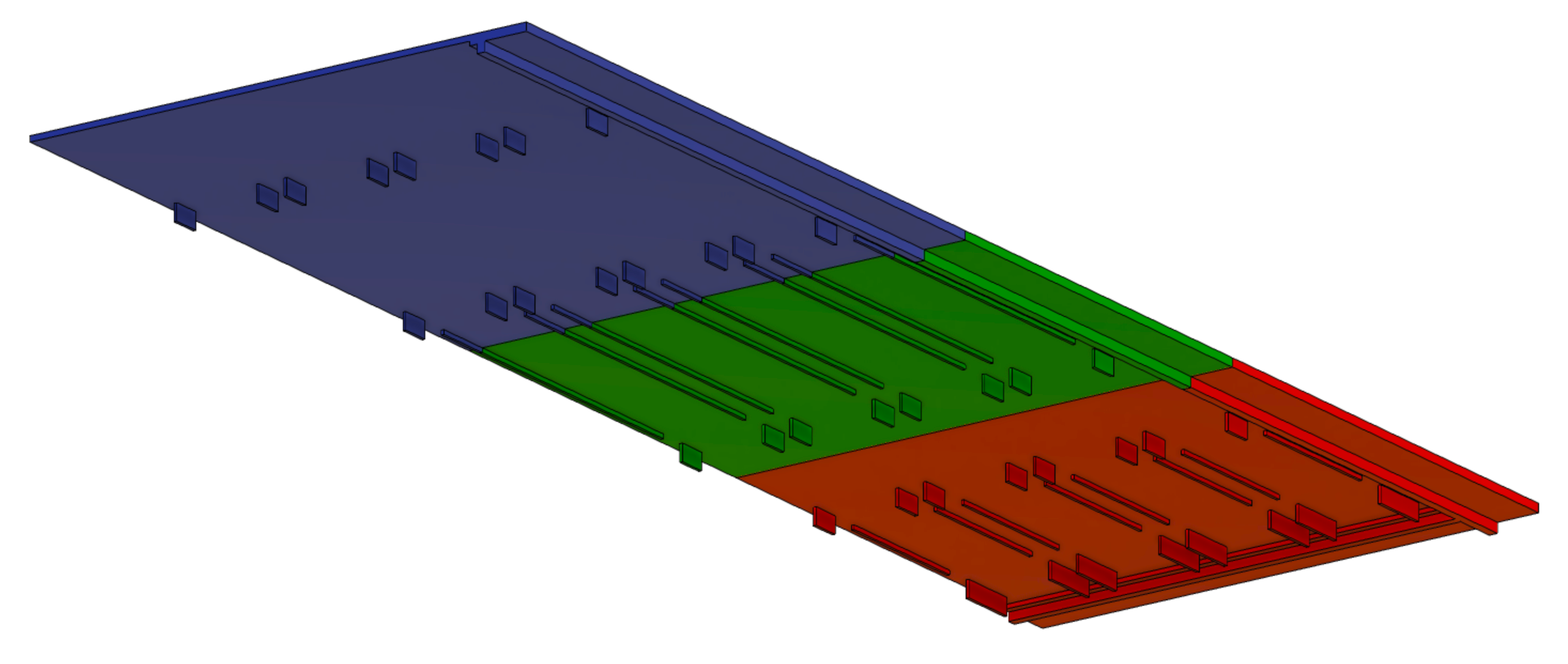
(32)
Prepare for tray B. I made a parametrized version of the tray, so
I can quickly make A, B, C and D.
        A   B   C   D
  -------------------
  dd1  30  30  30  60
  dd2  90  90  90 120
  dd3 180 180 150 210
  dd4 305 305 240 340
  dd5 445 445 375 500
  dd6 500 500 500 500
For now, we need the rgb parts:
b_right_bot.stl
b_right_mid.stl
b_right_top.stl
| 
|
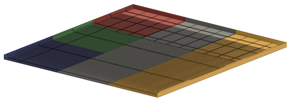
(33)
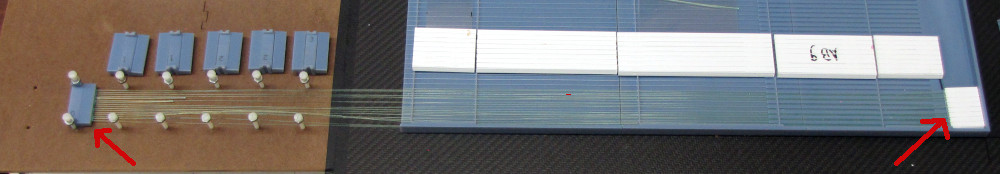
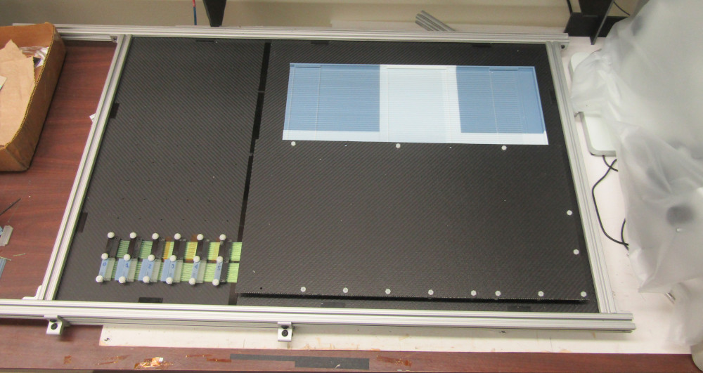
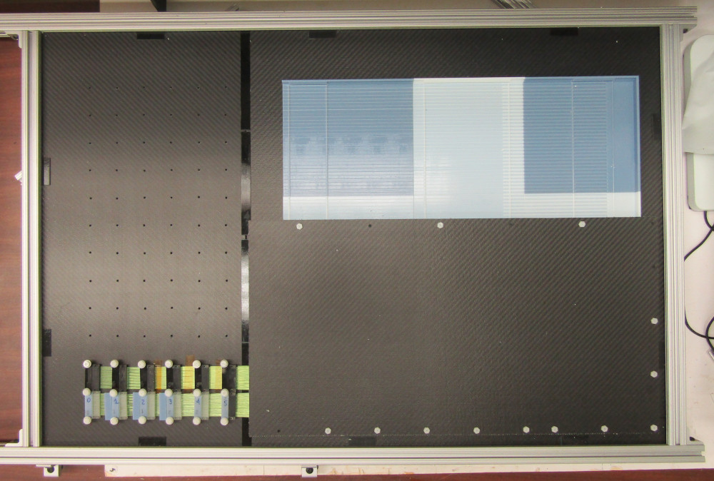
4 groups of 6 in place. Only the bottom two have fibers.
| 
|
(34)
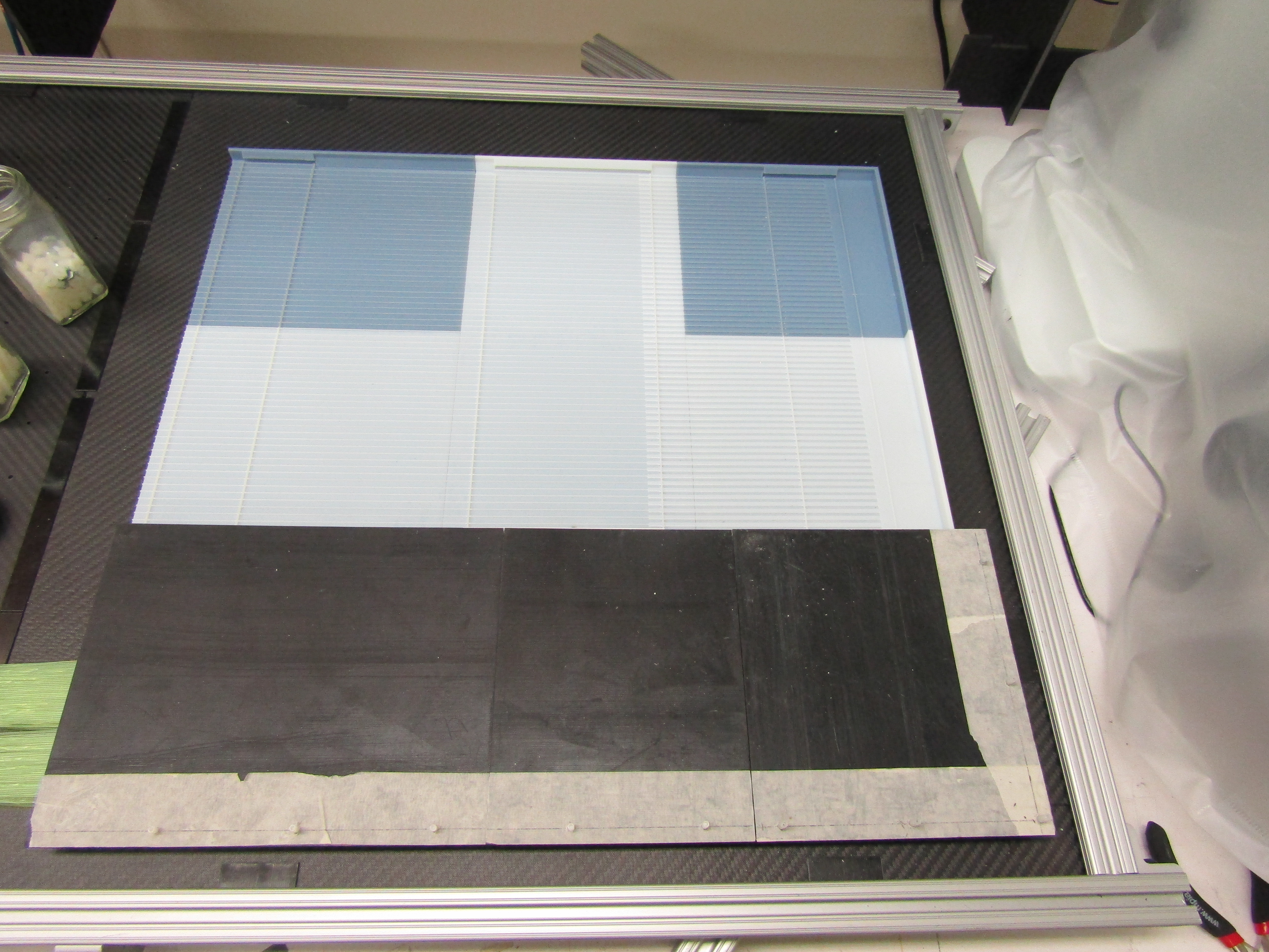
Top covers in place
| 
|
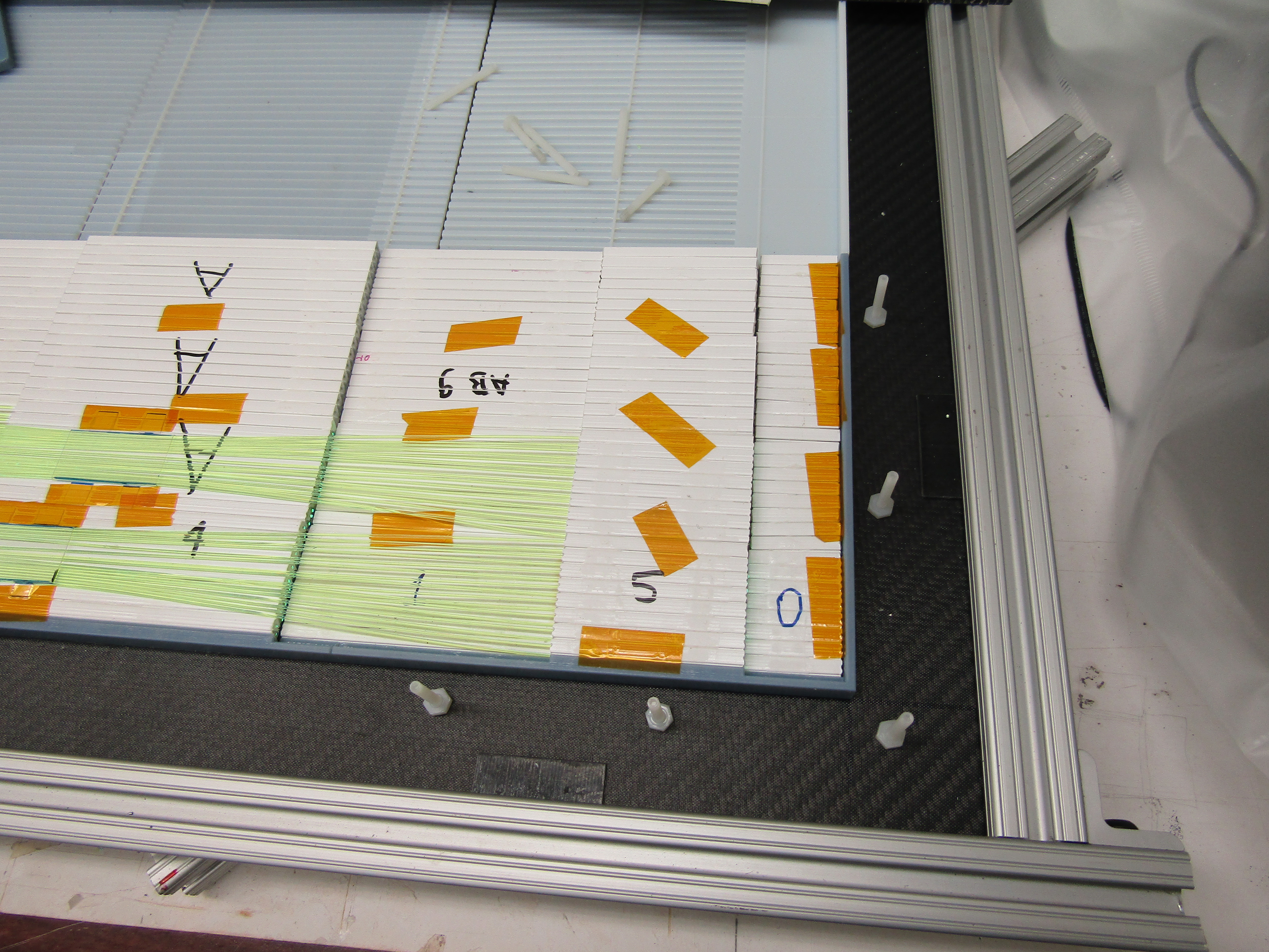
(35)
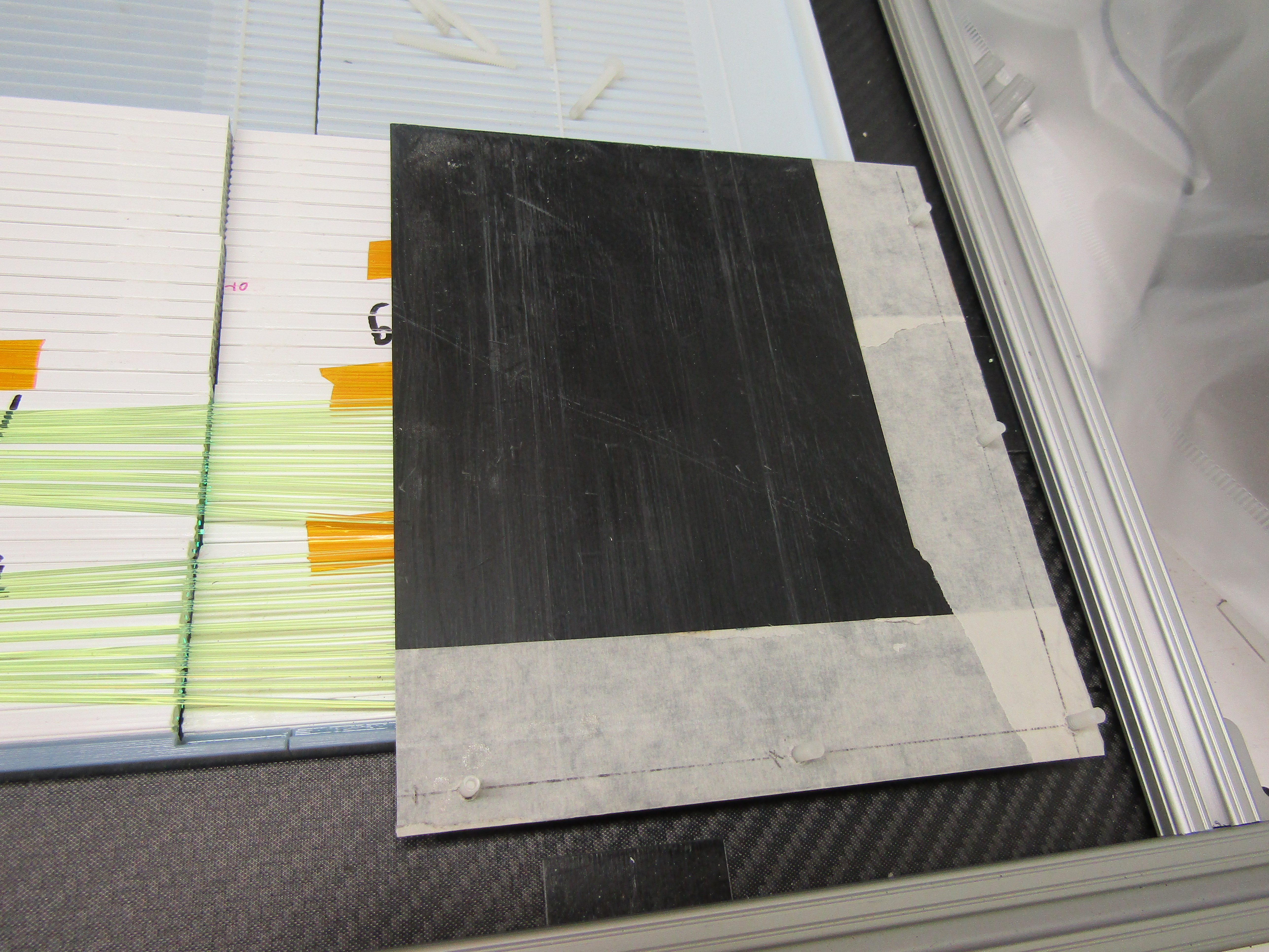
Partial top: 3 covers held in place with a carbon fiber panel. The panel is not the full width, it was a left over piece. Needs to be replaced
Now layer A can be flipped over and layer B will be constructed on the
other side.
| 
|
continue on the next page
|