Assembly tray (1)
|
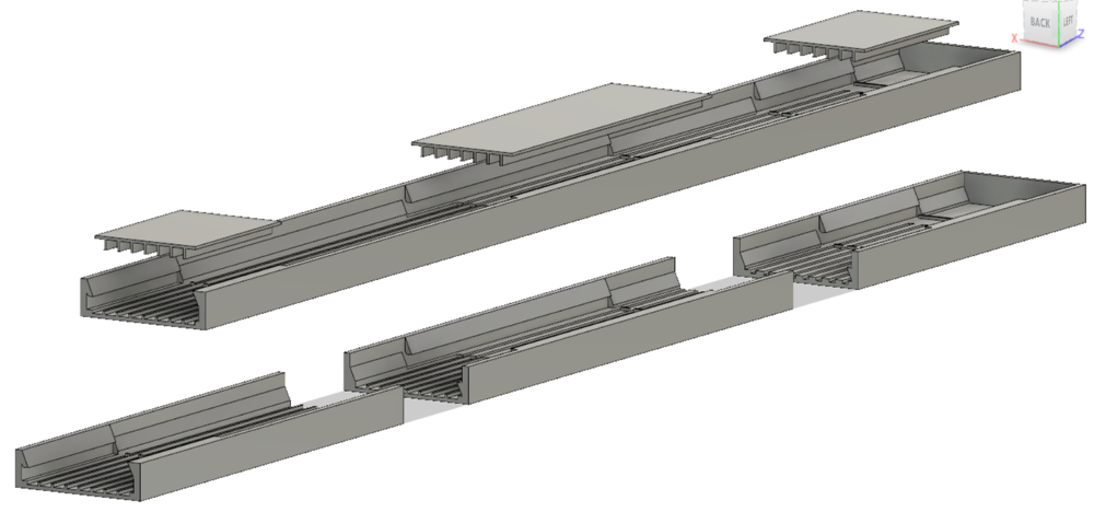
(1) Each tray (see section 36 here) is 50 cm long, but the printer has a 9" bed, so I cut the tray into 3 sections. The little platforms support the B,D,F bars. tray/tray1.stl tray/tray2.stl tray/tray3.stl tray/bridge1.stl tray/bridge2.stl tray/bridge3.stl
Look at these files here:
viewstl.com
| 
| ||
|
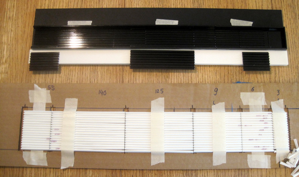
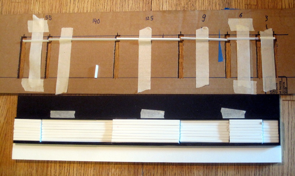
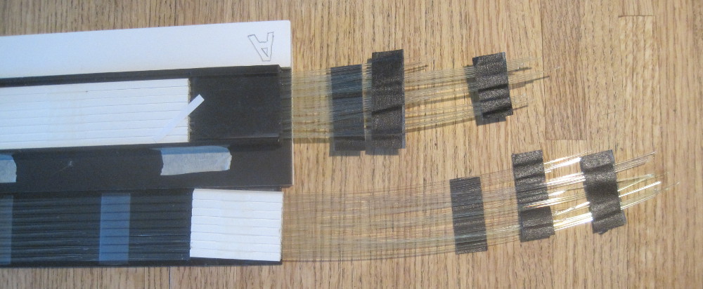
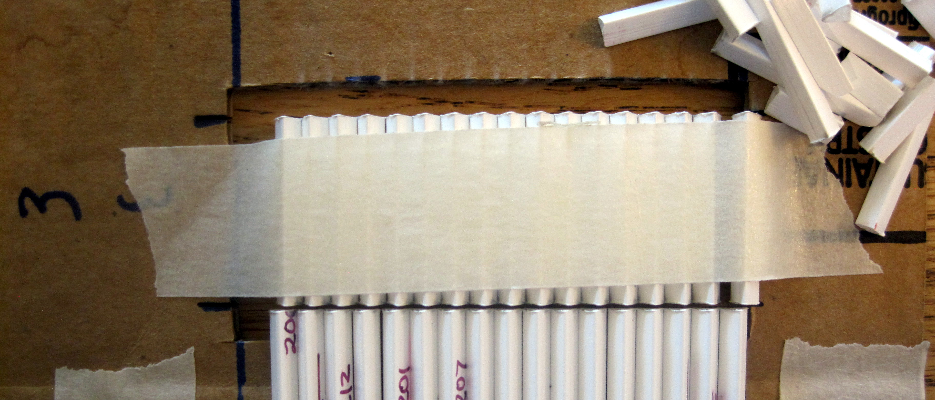
(2) Top: the tray assembled out of the 3 section, taped to some foam-core board.
Bottom: the bars taped to a support, and laser-cut into sections (from right to
left 30, 60, 90, 125, 140, 55mm).
| 
| ||
|
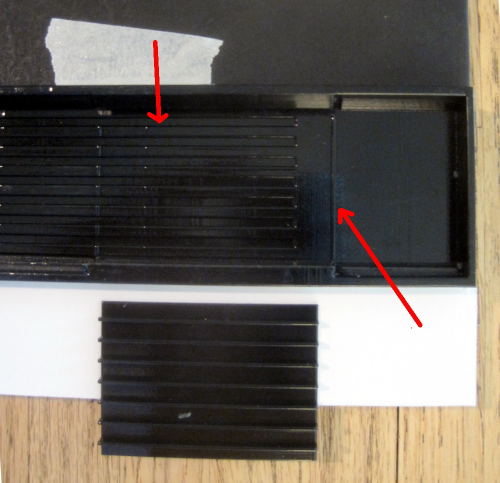
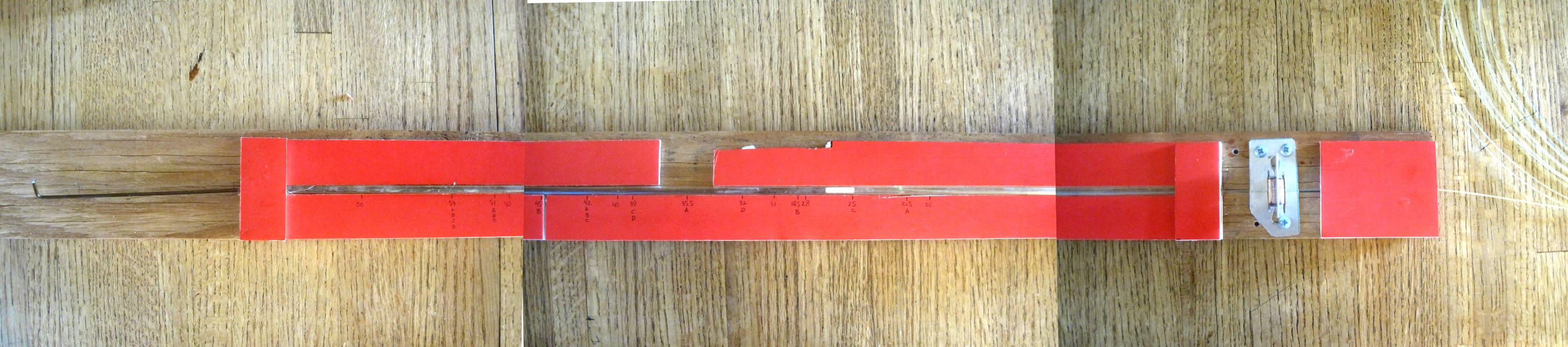
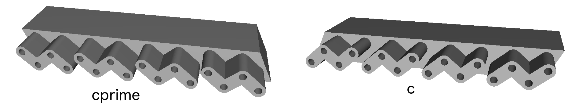
(4) First placed are to 30mm bars. There is a 1mm ridge to hold the bars in place. Also indicated are the 1mm deep grooves where the fiber pairs go. Here the grooves are 2mm wide, they widen to 4mm after the 90mm set of bars.
Note that this works for this 50cm prototype. For every group of bars, there
is one fiber pair every 5mm (the width of the triangular bar base), so at
the end of the 50cm prototype the groove width is 4mm, leaving a 1mm wall.
However, for the full
100cm model, we would need 6mm of space. So we would need to make the
fiber groove 2mm deep.
| 
| ||
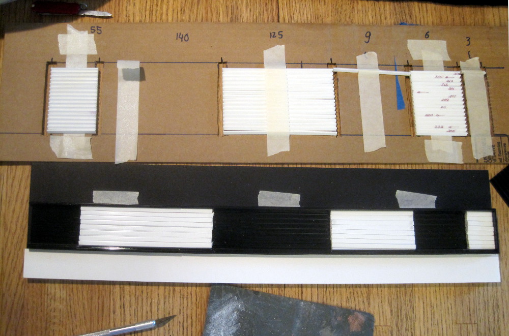
(5) Next place the other sets that go on the bottom (30, 90, 140mm). These also have 1mm ridges to hold them. These ridges are traversed by the grooves for the fibers, so the ridges turn into a row of nubs.
| 
| ||
|
(7) All groups have been placed. No fibers yet.
| 
| ||
|
(8) I took the whole thing apart, and re-assembled it, inserting 4 fibers in each of the groups. | 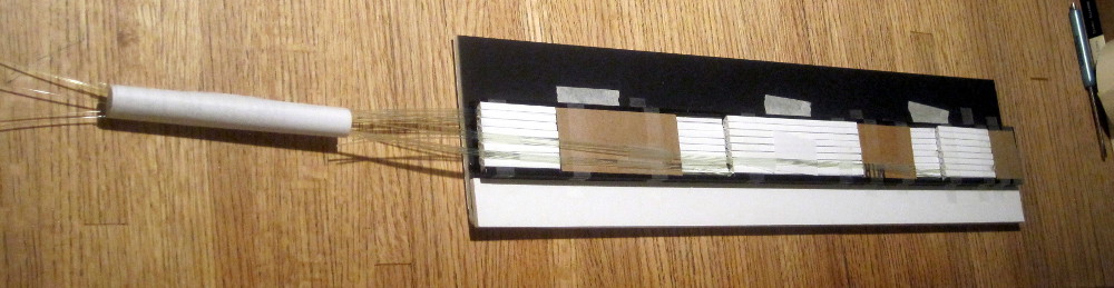
| ||
|
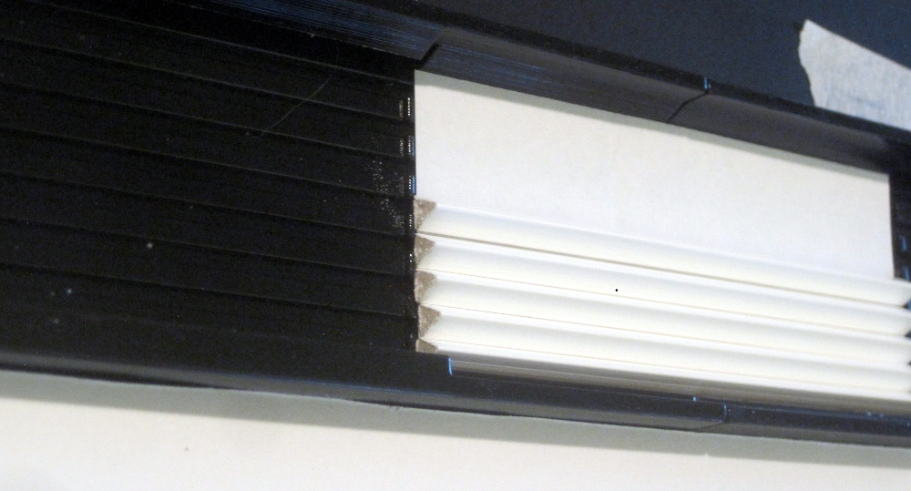
(9) A) Place the scintillators loosely in the guides. Take care that the orientation is correct - the triangles are not equilateral. I also look at both ends and point the cleanest-looking hole to the left. Place the caps over the top, and slide the assembly to the right. This ensures that the scintillators are all aligned and straight. If any of the gaps looks different from the others, check for a mis-oriented scintillator. | 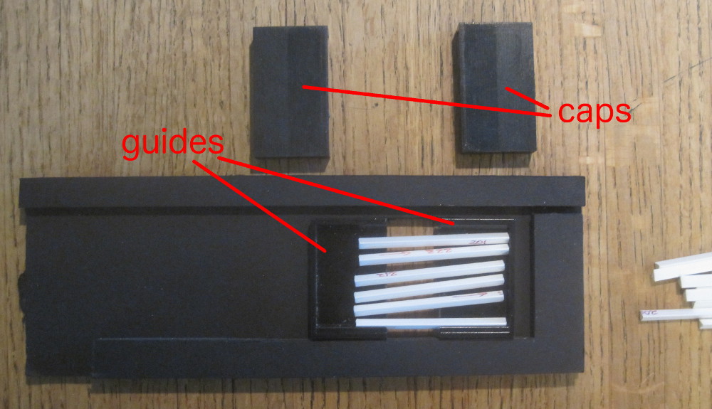
| ||
|
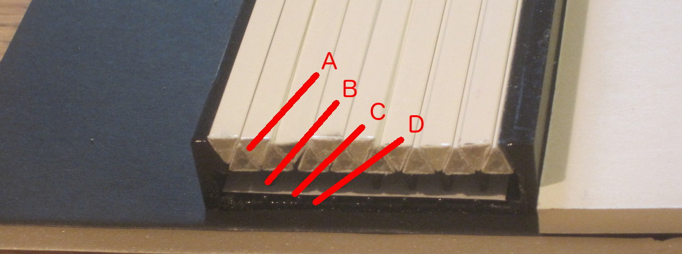
(10) B) Mix up some 5-minute epoxy, and lay down a ~1cm stripe of glue. Rub it down - in the end we want glue mostly in the grooves, and none on top. Also wipe away any epoxy that went down the sides. (The spacers are for when you are doing the really short scintillators.) | 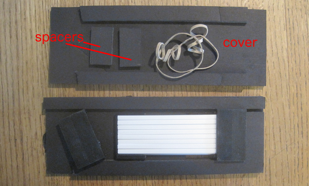
| ||
|
(11) C) Place the cover on top, and secure with 2x2 rubber bands. Flip the jig over, and lay down epoxy on the back side. Again remove any extra epoxy. Set the timer for 10 minutes. Disassemble the jig. Check for excess glue. | 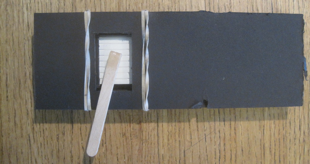
| ||
|
(12) The connector-coupler-connector assembly takes up 30mm, and we leave 30mm between adjacent connector assemblies. We assemble blocks 1,3,5 into the tray, and blocks 2,4,6 onto the top cover. This means we cut WLS fibers as follows:
   Scint.block:     1     2     3     4     5     6        total
-------------------------------------------------------------------
   tray A          54.0  51.0  51.0  42.0  35.5  21.5    255x16=41m
   tray B          54.0  51.0  51.0  45.0  42.0  28.5           44m
   tray C          54.0  51:0  51.0  42.0  39.0  25.0           42m
   tray D          54.0  48.0  48.0  39.0  32.0   x             36m
-------------------------------------------------------------------
                                                               163m
| 
| ||
|
(13) We need to cut 368 fibers to exact length. Here is a fixture for that: the WLS fiber feeds into a thin plastic hose from the right, is passed over a cutting fixture into another tube, until it hits a stop. The stop is a rod (coat hanger wire), inserted from the left, with some tape at the end. The cutting fixture is a narrow slot to guide a razor blade. This way you can set the stop, cut 16 fibers exactly the same length, then reset the stop and cut the next set. 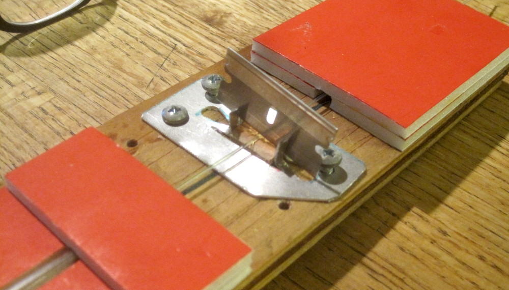
| 
| ||
|
(14)
| 
| ||
|
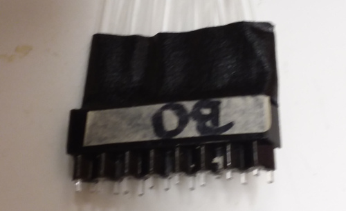
(15) Use the polishing block, plus a 1mm spacer (orange) to assemble the fibers into the connectors. Having cut the fibers with the razor blade and guide, the ends are fairly square, and a 1 mm protrusion is sufficient. I dip the fiber ends into 5-minute epoxy, and slide them in. | 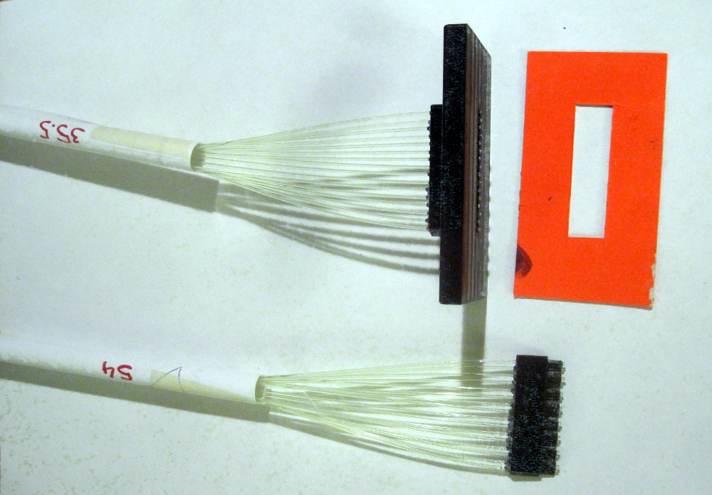
| ||
|
(16) Polish the ends, first on 600 grit paper, with the double-orange spacer (1mm), then with the single-orange spacer (0.5mm), then with the single-paper spacer (100 um). Switch to the pink polishing paper and the single-paper, then without any spacer. Use the flat steel plate under the sanding paper, and use the bundle holder to keep the fibers from flopping over. | 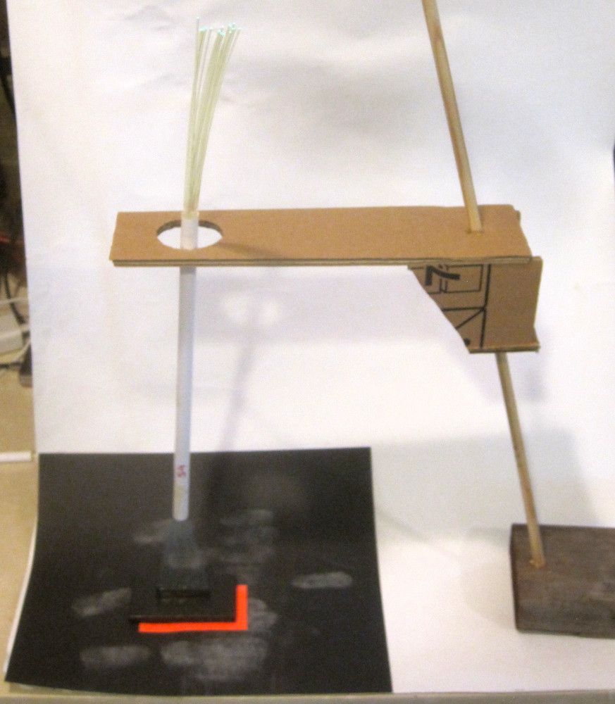
| ||
|
(17) Insert the fibers into the scintillator block (on the table - the block is not yet in the tray). Check that no fibers are crossed. Lay the scintillator block (this is for blocks 1, 3, 5) into place into the tray, and guide the fibers into their grooves. Initially, hold down the fibers with the little foam blocks, so they can still slide a little. When they are all in place all the way to the end, tape them down with scotch tape. When doing the top (blocks 2, 4, 6), lay down some roll-on adhesive to hold the blocks in place. | 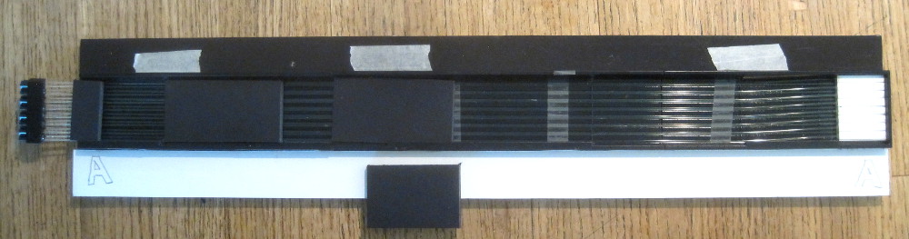
| ||
|
(18) All 6 block are finished and installed, 3 into the tray, and 3 onto the cover. Next, put the bridges into the tray, so that the 3 blocks from the top are supported, and place the top onto the tray. | 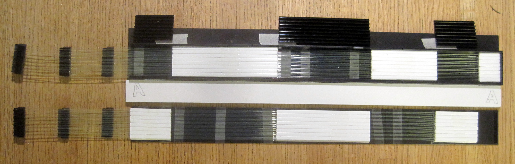
| ||
|
(19) (27 Oct 2019) The "A" unit finished. Three more to go. | 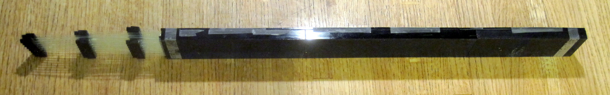
| ||
|
(20) The connector-coupler-connector assembly takes up 30mm, and we leave 30mm between adjacent connector assemblies. We assemble blocks 1,3,5 into the tray, and blocks 2,4,6 onto the top cover. Now, however, We want to alternate top, bottom connectors, and keep a few mm between connector groups. This means we cut WLS fibers as follows:
   Scint.block:     1     2     3     4     5     6        total
-------------------------------------------------------------------
   tray A          54.0  54.5  52.0  46.5  37.5  27.0    272x16=44m
   tray B          54.0  54.5  52.0  49.5  44.0  34.0           46m
   tray C          54.0  54.5  52.0  46.5  41.0  30.5           45m
   tray D          54.0  51.5  49.0  43.5  34.0   x             38m
-------------------------------------------------------------------
                                                               173m
| 
| ||
|
(21) The LED array should match the fiber positions, 5mm pitch horizontally, and 3mm pitch vertically between odd and even positions. One of the rows of the array should be on the very edge of the carrier board, since the next block of scintillators overlaps in the vertical direction by 1mm. There should be 2 versions, which are mirrors of each other. | 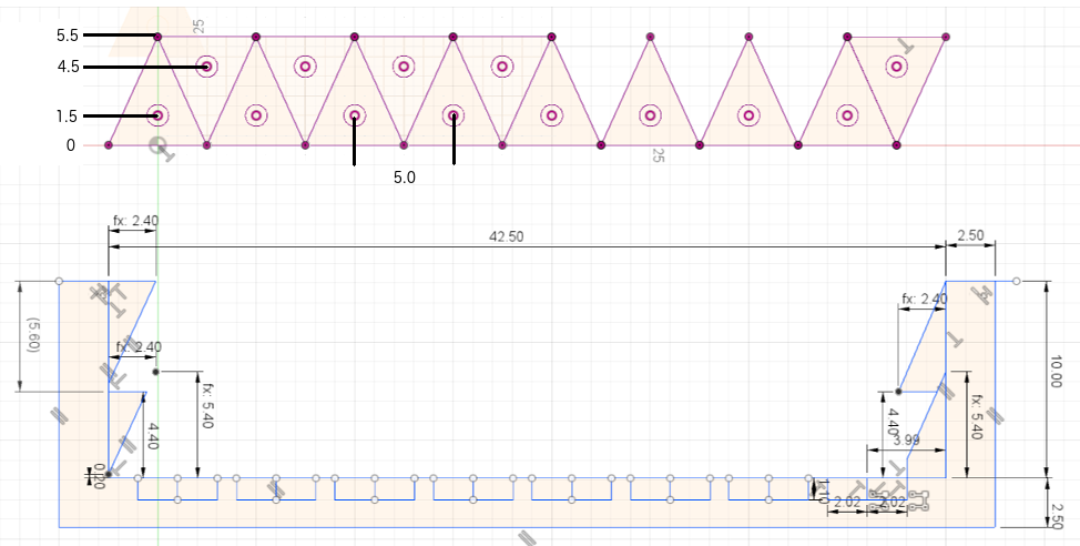
| ||
|
next page | |||
Hubert van Hecke Last modified: Wed Nov 20 12:49:46 MST 2019