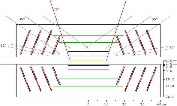
 This image shows the VTX geometry as currently in CVS (see also
this page..
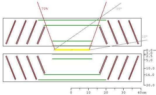
The outer barrel layers (green) and the first endcaps (red) almost touch, and
routing of cables and cooling services from these layers to the outside would be
problematic.
This image shows the VTX geometry as currently in CVS (see also
this page..
The outer barrel layers (green) and the first endcaps (red) almost touch, and
routing of cables and cooling services from these layers to the outside would be
problematic.
In Yellow is indicated the 'interaction diamond', at x=y=0 and z=+-10cm. From the endpoints of this diamond, lines are drawn indicating the acceptance of the Muon arms in gray (12-35° and 10-35°) as well as of the central arms in red (eta=+-0.35).
The outer barrel layers extend substantially outside of the central arm acceptance. Here we explore possible different arrangements of the barrel strip components such that these integration issues can be ameliorated.
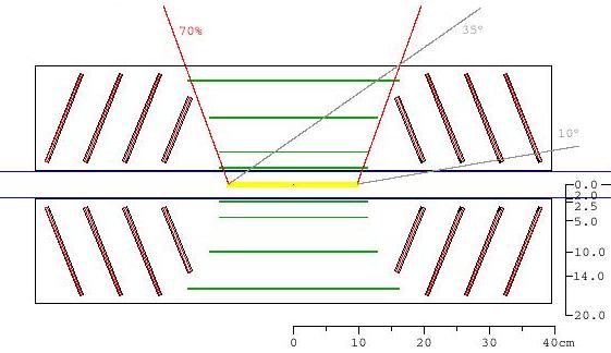 In the configuration shown on the right, the length of the barrel strip layers
has been modified,
and the radius if the outer barrel is increased. The geometry changes are
summarized in the table below.
In the configuration shown on the right, the length of the barrel strip layers
has been modified,
and the radius if the outer barrel is increased. The geometry changes are
summarized in the table below.