gif
jpg
png
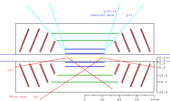
muon arm acceptance

In the drawing below, a blue line is drawn at angle y=1, along the edge of
layers 2,3 and 4 of the barrel. The first two silicon endcaps are reduced to
start 1 cm
away from this line, in order to allow for support structures, cooling
services and power and signal cables. Also in blue are lines indicating the
central arm acceptance. On the bottom half, red lines indicate the muon arm
acceptance for an 'interaction diamond' of z=+-10 cm.
|
Formats available:
gif jpg png muon arm acceptance |

|
|
Cables for the inner 2 layers (pixels) of the barrel added. L
The outer 2 barrel layers (strips are not shown.
The central section of the interaction diamond, z=-10-+10 cm, is represented by the yellow line. The red and black lines lines indicate the North Muon Arm acceptance. The black lines are at 10°, and are drawn from interaction verticies at -10, 0, and +10 cm. The red lines are at 35°.
Click here for the full-size gif
|

|
Note that layers 3 and 4 of the barrel have greatly expanded and moved out in radius.
|
With lines indicating the Muon arm acceptances. The yellow line on the beam axis shows a +-10cm
interaction diamond, and the
gray lines at 10, 12, 35 degrees show the muon acceptance corresponding to the edges of this diamond.
gif jpg png xcf (Gimp) gsdfgs sg sdgsdfgsdf gsdf gs dfgsdfgsdfg sdfg sdfgsdfgsdfgsd fgsdfgsdfgsdfgs d |

|
|
Without Muon lines
gif jpg png |

|
|
gif jpg png xcf ps |

|
| This image is from a presentation that Hytec engineers gave in December 2003. Note angles are measured from z=0. | 
|
