After the Geant 'nan bug' was fixed, resolutions turned up
worse than before. Likely the screwup of the materials definition in SVX
(aircold, carbon-carbon, ...) made these materials effectively zero-mass,
leading to
overly optimistic resolutions. Most of the mass seen by endcap-traversing
particles is in the carbon of the support panels:
|
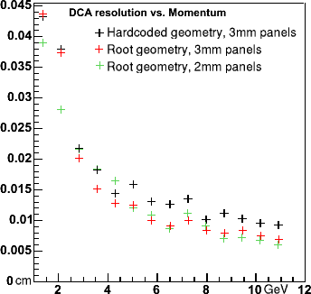
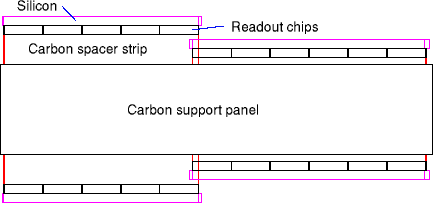
| The current endcap layers consist of a 3mm carbon support
panel (so that 3mm cooling tubes could be embedded). On either side are mounted
narrow carbon spacer strips (same width as the readout chips, 3.8mm),
readout chips
down the spine of the silicon, and finally the silicon.
The 3mm carbon panel is the main culprit limiting the resolution of the
detector.
| 
|
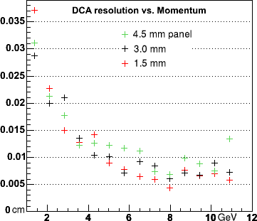
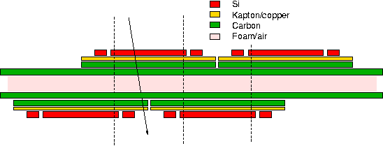
| The proposed stack has Si and chips mounted side-by-side,
on top of a 200 μm Kapton/copper bus, on top of 0.5mm carbon.
These units are
placed on the front/back of a panel that carries the heat to the disk
perimeter,
and is here drawn as 2 skins of 0.5mm pyrolytic graphite, with a low-density
core. Assume there are 6 100μm glue layers (si-bus, bus-carbon and
carbon-carbon).
If we assume Kapton/copper and glue are roughly equivalent to carbon, a typical
particle sees 3mm of carbon and 300μm of Si.
| 
|
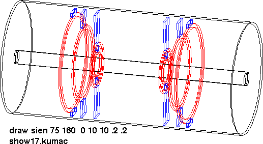
While we were looking at materials, I revisited the mass in front of the endcaps.
The barrel supports had been modeled as 5×5 mm carbon rings.
They are actually half-circles, with support posts going up and down in a 8° angle.
The rings are also thicker and wider.
| barrel # | Rmin | Rmax | width
| | 1 | 40 mm | 46 | 6.35
| | 2 | 65 | 75 | 6.35
| | 3 | 112.5 | 127 | 6.35
| | 4 | 152 | 165 | 6.35
|
Pisa volume names: SISP for the rings (red), SISQ for the posts (blue)
| 
|
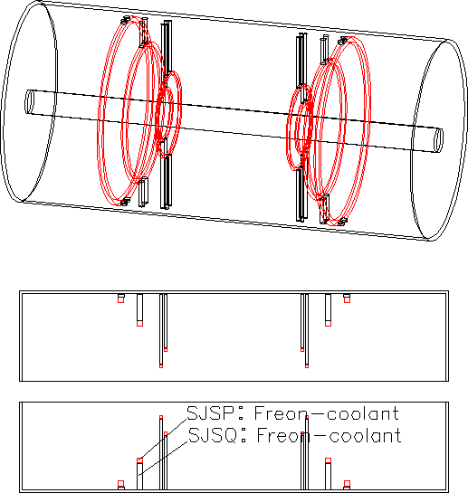
The cooling tube manifolds are also semi-circular, with feeds going up and down.
The individual tubes sitting on the ladders are 4mm OD, 0.356mm wall aluminum. The manifolds
have diameters such that the total cross-sectional liquid area is preserved for each layer,
and thus manifold tube diameters increase by layer.
| barrel # | <R> | ID
| | 1 | 48 mm | 4.9
| | 2 | 78 mm | 6.4
| | 3 | 127 mm | 9.4
| | 4 | 170 mm | 10.4
|
In the model, the (senmi) circular portions of the manifolds are modeled by rings with square
cross sections and area matching the round tubes, and the vertical pieces are round tubes.
As for material, I made these solid coolant (Freon), though they have 0.5mm Al wall.
Pisa volume names: SJSP for the rings (red), SJSQ for the vertical tubes (black)
| 
|
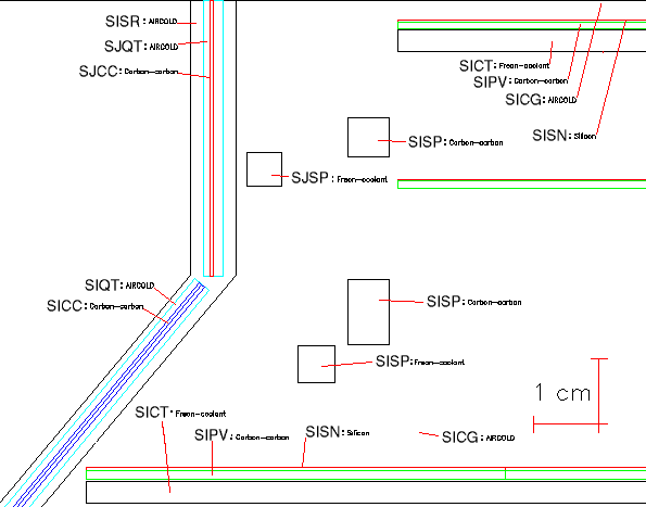
| This cross section, parallel to the beam pipe (black line on top) shows the ends of
barrel layers 1,2,3, plus cross sections of the support rings and cooling mainfolds.
In order to accomodate these items, I had to shorten SISR, the 'support cone' that
represents barrel cables, and carbon support for the endcaps. SJCC represents the
barrel-1 cables,
now thinned to 0.5mm carbon (was 1.0). SICC is now 2×0.5mm carbon, representing additional
cables from barrel2, 3 etc.
| 
|