Placement of modules on the half-disks


Previous: ??   |   Index   |   Next: Disappearing hits


Northwest quadrant (SCM4) showing the SI16 half-disk mother volume, and 24 modules in red. Are the modules placed correctly?
          SCM2           West          SCM4
          +-------------\    /------------+
          | si06 08 10   \  /   16 18 20  |
          |            12    14           |
  South   +---------------  --------------+   North
          |            11    13           |
          |   05 07 09   /  \   15 17 19  |
          +-------------/    \------------+
          SCM1           East          SCM3
SI16 is the half-disk corresponding to station2 in the Northwest quarter of the FVTX. The (Geant) picture shows the outline of the NW half-cage, and superimposed are two horizontal sections through SI16, one at z=0cm in red, and one section near the top of the half-disk in dark green. You can see that the support disk sticks out across the mid-plane, and that modules go from top to bottom (=-phi) back-high, front-high, back-low, front-low, where 'front' is the side facing z=0.

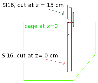
As an aside, you can also see that the front-low modules intersect the support plane. This also needs to be investigated.

31 Aug 2010 (HvH and AB private) software version.

Checking the Hytec mechanical model, the order is back-low, front-high, back-high, front-low. The image shows station 2 seen from the top, with only the support plate and the first four modules made visible.

This order is the same for stations 2,3,4. Station 1 is back-high, front-low, back-low, front high, and we reproduce this in Pisa.

svx_fvtx.f has been modified to have the offsets in the proper order. Also, the distance of the modules to the support plane is now set to the actual values, 0.9mm for the low supports, and 4.9 mm for the higher ones. Note the actual thermal support pieces are not in the MC.

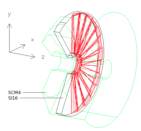
As in the Hytec model, all modules are rotated such that the edge of the first Si module makes an angle of 2.322° with the edge of the support panel. Module numbering is such that on SI16, module 1 is at the top, proceeding in -phi direction to the bottom.

The arrows show 1 cm scales, the z-scale is stretched.

angle between the support plane edge and the edge of the sensor is:
 st 1: 1.670 deg
 st 2: 2.322 deg
 st 3: 2.322 deg
 st 4: 2.322 deg


back


Hubert van Hecke
Last modified: Tue Jan 4 17:28:43 MST 2011