This is a short description of the content of file ancsvx.root, for just the variables that we've used.
   0 :TRACK     : track number
   1 :NFILE     :
   2 :PTOT      :
   3 :PTHETA    :
   4 :PPHI      :
   5 :R_VERTEX  :
   6 :Z_VERTEX  : event vertex
   7 :THET_VER  :
   8 :PHI_VER   :
   9 :ITPARENT  :
  10 :IDPARENT  :
  11 :IDPART    :
  12 :ITORIGIN  :
  13 :IDORIGIN  :
  14 :IHIT      :
  15 :LAYER     : 1-4 is the barrel, 5-8 is the South endcaps, 9-12 the North endcaps
  16 :THETA     :
  17 :PHI       :
  18 :XGLOBAL   : global x coordinate
  19 :YGLOBAL   : global y coordinate
  20 :ZGLOBAL   : global z coordinate
  21 :PMOMX     :
  22 :PMOMY     :
  23 :PMOMZ     :
  24 :IPC123    :
  25 :PC1THETA  :
  26 :PC1PHI    :
  27 :PC1RDIST  :
  28 :PC1ZDIST  :
  29 :PC2THETA  :
  30 :PC2PHI    :
  31 :PC2RDIST  :
  32 :PC2ZDIST  :
  33 :PC3THETA  :
  34 :PC3PHI    :
  35 :PC3RDIST  :
  36 :PC3ZDIST  :
  37 :DELE      : energy deposited
  38 :XLOCIN    : local x inside silicon for track entry point
  39 :YLOCIN    : local y inside silicon
  40 :ZLOCIN    : local z inside silicon
  41 :XLOCOUT   : local x inside silicon for track exit point
  42 :YLOCOUT   : local x inside silicon
  43 :ZLOCOUT   : local x inside silicon
  44 :HITVOL0   :
  45 :HITVOL1   :
  46 :HITVOL2   :
  47 :HITVOL3   :
  48 :HITVOL4   :
  49 :HITVOL5   :
  50 :NHIT      :
  51 :X0_EVENT  :
  52 :Y0_EVENT  :
  53 :Z0_EVENT  :
  54 :B_IMPACT  :
  55 :EVENT     : event number
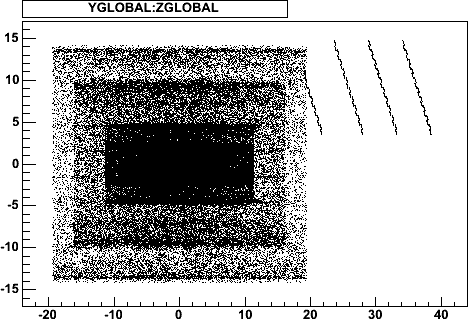
| root [4] AncSvx->Draw("ZGLOBAL:YGLOBAL")
produces this picture: This file contained 11 central AuAu events, and you can see the silicon barrels, as well as the 4 LDRD endcap planes in the tilted configuration. You can see that these consist of 12, 20, 20, 20 silicon modules, staggered front-back. | 
|
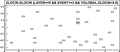
| This shows that when we look at the bottom module of the the first endcap plane (layer 9), that this is a silicon plane about 7cm wide and 6mm high, and that there are 32 track entry points in event 3. | 
|
back