sPHENIX Finger Scintillators
|
Picture
from here
I made a pair of scintillator bars (left over from
this FNAL detector
From the left:
| 
|
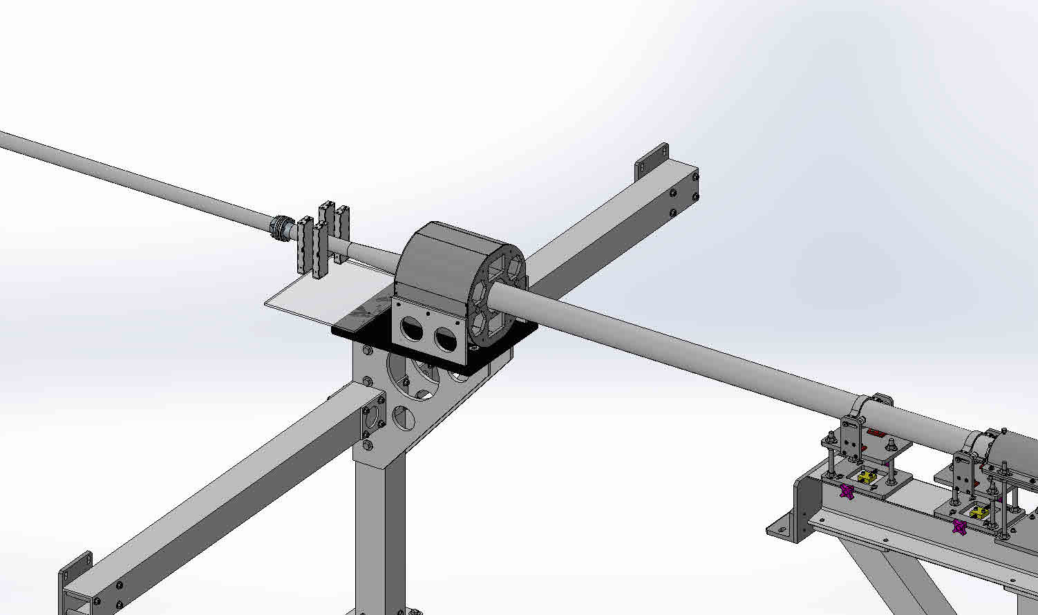
Proposed placement | 
|
Cut file for a 2-bar box. There are added tabs here and there for cable ties. These can be snapped off if not needed. For assembly, it assumes that the bars+wls fibers are shipped separate from the spools of fiber pairs + connectors. Five of these fit on a 1x2-foot black 1/8" plexi.
I laser-cut some prototypes out of masonite and plexi. The bars slide in, and the cover goes in and is held by two 6-32 screws on the sides. Those 2 pieces slide in and keep the bars from moving around inside. | 
|
|
Assembly looks like this:
You have the long fibers rolled up with sleeves, connectors on both ends, and on the detector end also a rubber grommet over the end of the sleeve. Then you have the detectors with the WLS fibers and the connector attached, and the empty box.
|

|
| Readout box: the middle plate has 16 pairs of holes where the SiPM
leads poke through (one SiPM shown). Then a plate lies on top, with
holes to center the fibers on the SiPMs, then black foam to hold the
fibers in place.
Below the middle plate the wires get soldered on, and led out through a hole in the side, and the bottom is closed with another plate.
| 
|
|
boxes_plate.dxf
fatplate.dxf
| 
|
| The fiber wheels are from here | 
|
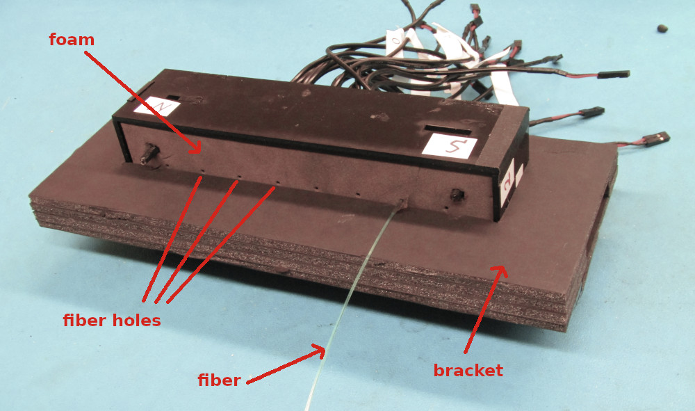
| Readout box, fiber side: The center plane (not visible), which holds the SiPMs, has 4 8-32 threaded rods, fixed with nuts on both sides. The nuts on the SiPM side are sanded down to a thickness of 2.1 mm, equal to the height of the SiPMs. A plate with 1mm holes goes over the SiPMs, and is fixed with 4 nuts. A piece of dense foam, with the exact same geometry as this plate (including holes for the 8-32 rods, and holes for the fibers) sits flush on top of that. The rows of fiber holes are 20 mm apart, and a foam-core-board bracket fits over the box and sits between the rows of fibers. This bracket can be slid off (in one direction only) One fiber is shown inserted. It has a small piece of tape 17 mm from the (polished) end. If the fiber slides in 17mm, this indicates that it went through the foam and the SiPM cover plate, and touches the SiPM.
Since the fiber is flush with the bracket surface, it can now be fixed
in place with a piece of tape. Same for the 8 fibers on the other
side
| 
|
| Readout box, wire side: If you slide the bracket off, you can unsrew the cover plate. I noticed that the ground of SiPM #1 is not soldered on. I did not manage to solder this connection, the flux in the solder was not sufficient to establish a 'wet' contact with the solder, it just beaded off. Maybe a more aggressive flux, or a fresh cable... | 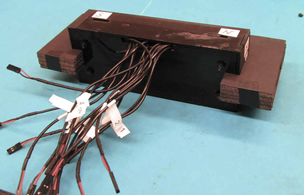
|