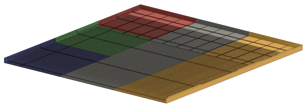
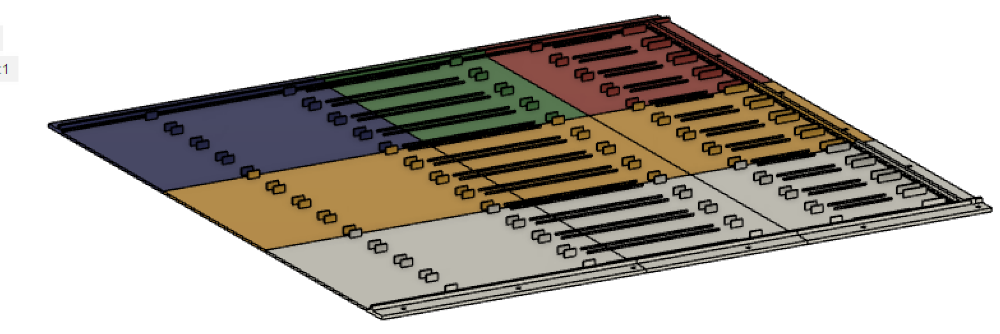
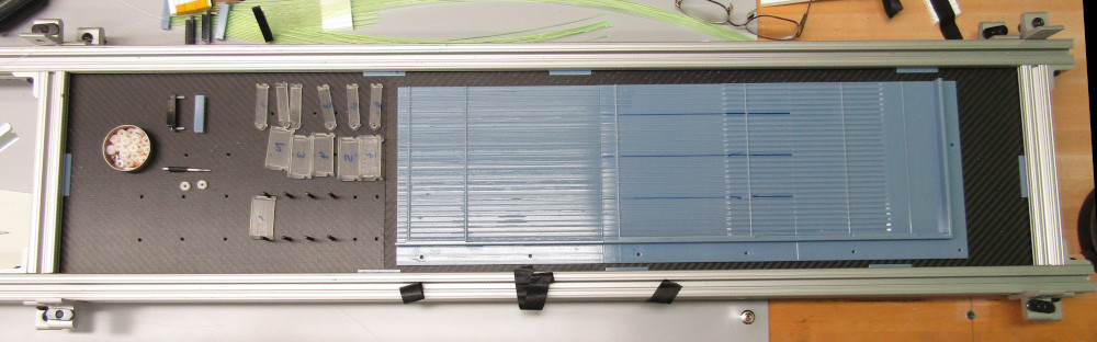
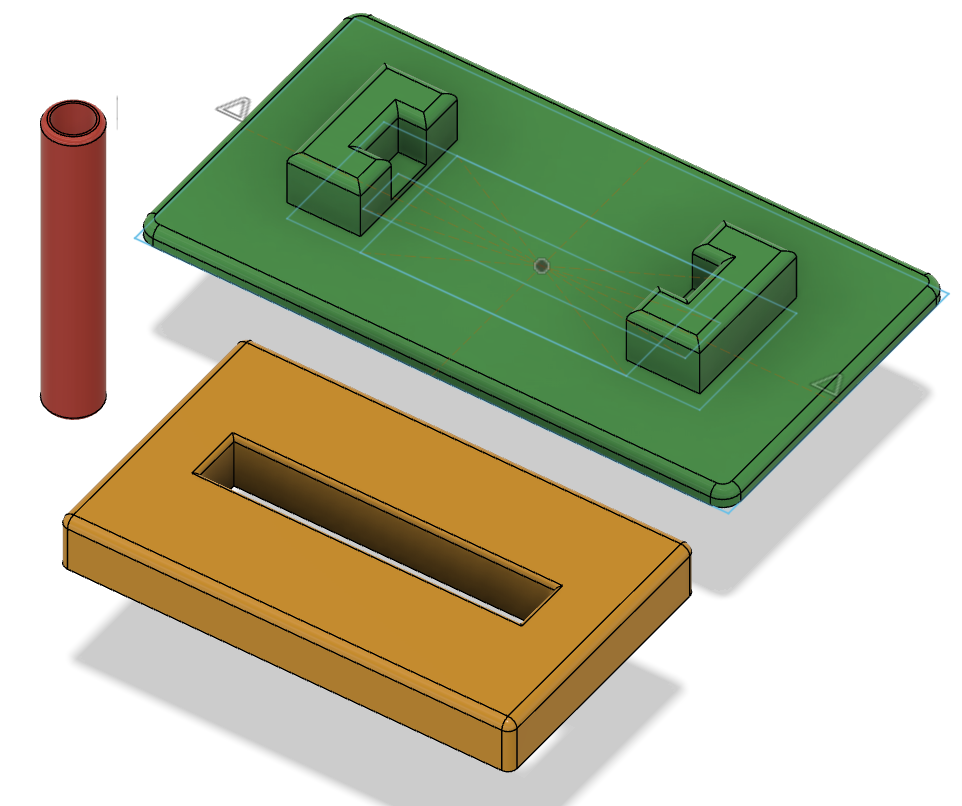
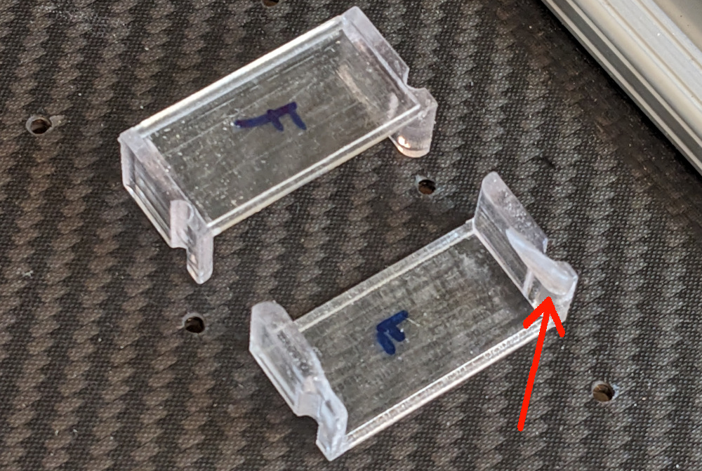
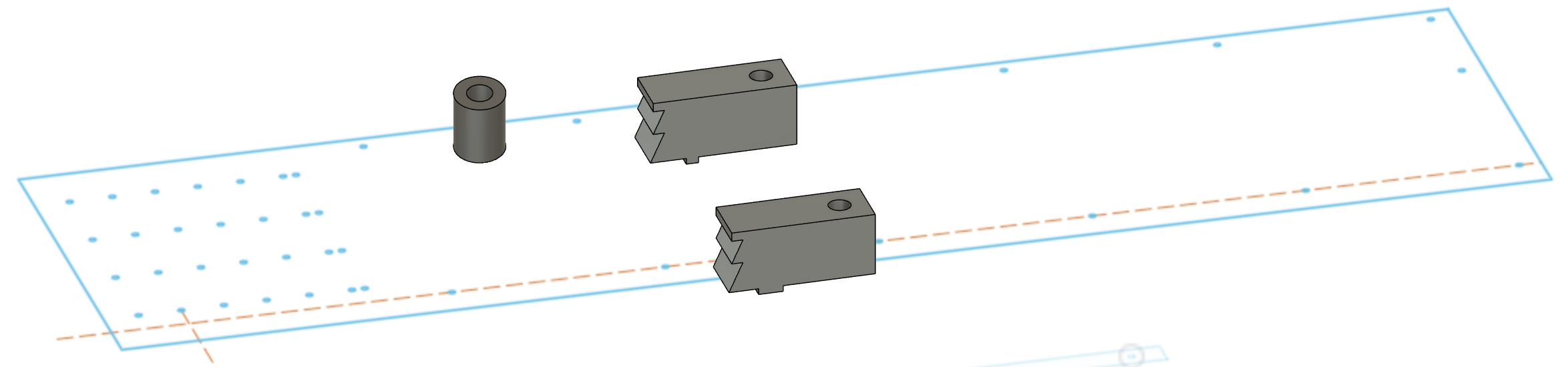
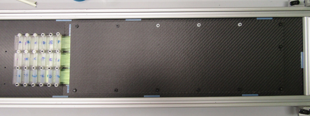
Trays
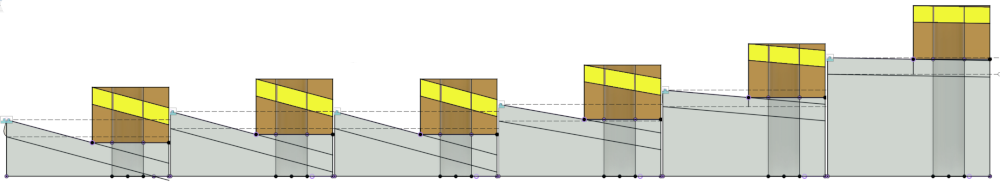
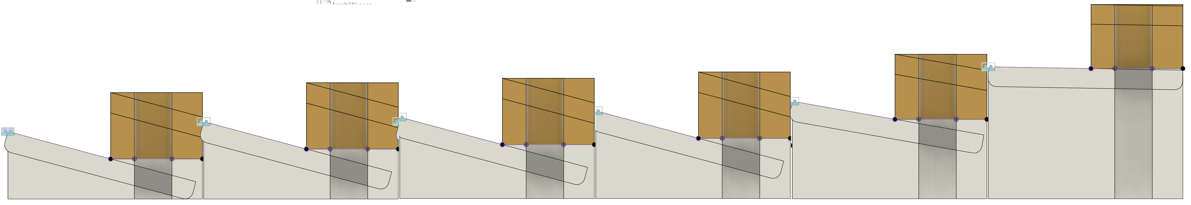
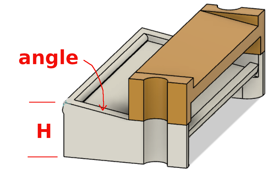
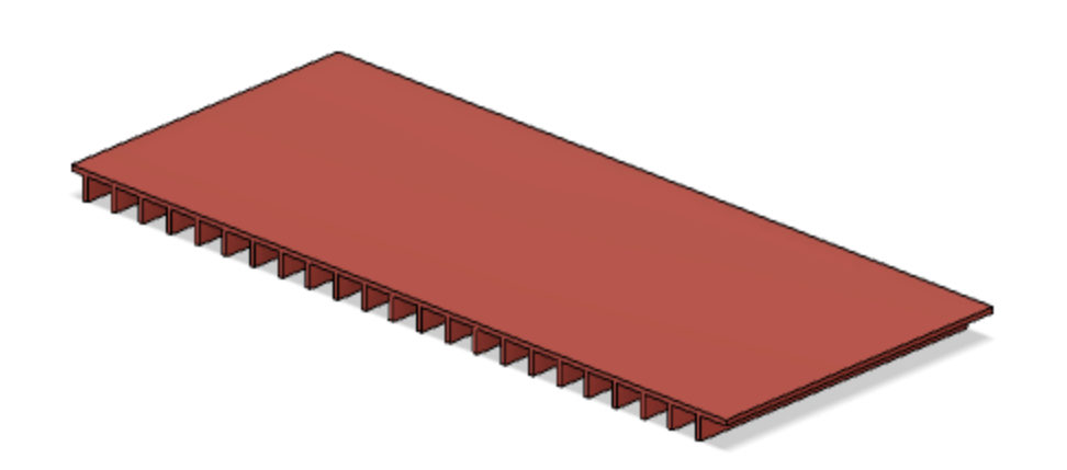
I made a parametrized version of the tray (in Fusion, lhcb->layerb), so
I can quickly make A, B, C and D. The parameters correspond to the
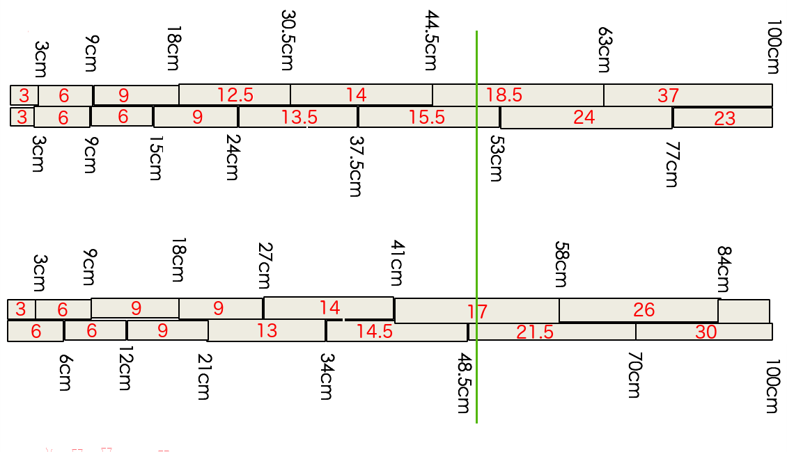
boundaries between blocks.
(notes)
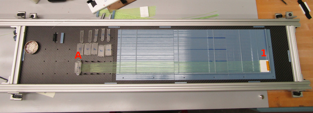
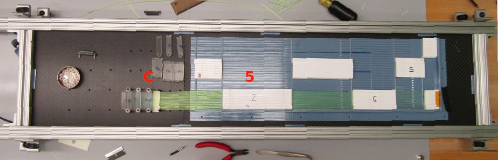
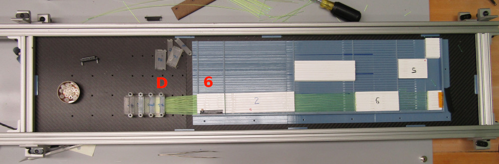
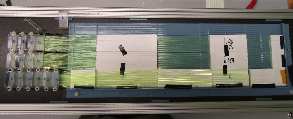
        A    B   C    D
  ---------------------
  dd1  30   30  30   60
  dd2  90   90  90  120
  dd3 180  150 180  210
  dd4 305  240 270  340
  dd5 445  375 410  500
  dd6 500  500 500  500
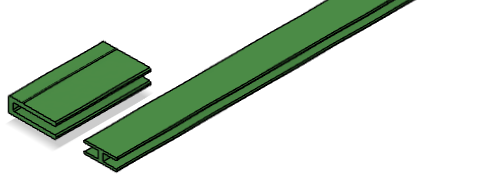
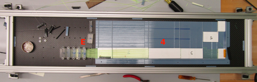
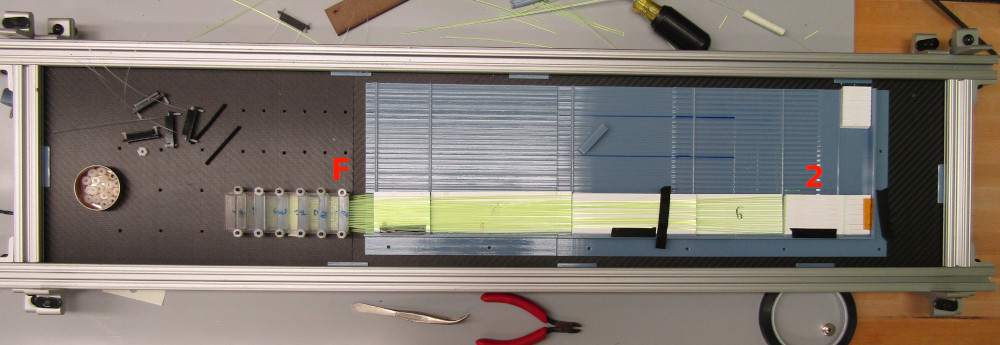
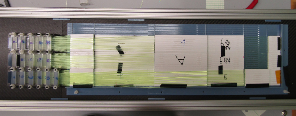
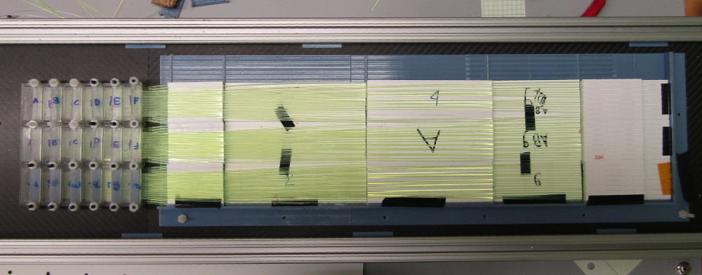
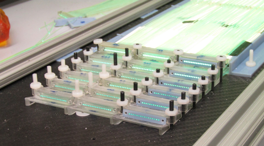
For A and C, we need the yellow parts, for B and D, the RGB parts.
layera_1.stl,
layera_2.stl,
layera_3.stl,
layerb_7.stl,
layerb_8.stl,
layerb_9.stl,
layerc_1.stl,
layerc_2.stl,
layerc_3.stl,
layerd_7.stl,
layerd_8.stl,
layerd_9.stl,
| 
|

