![[Back]](../../../gifs/arrow.marble.left.gif)
|
![[Up]](../../../gifs/arrow.marble.up.gif)
|
![[Next]](../../../gifs/arrow.marble.right.gif)
Previous page
| Up to the index
| Next page
| |
![[Back]](../../../gifs/arrow.marble.left.gif)
|
![[Up]](../../../gifs/arrow.marble.up.gif)
|
![[Next]](../../../gifs/arrow.marble.right.gif)
Previous page
| Up to the index
| Next page
| |
Oak Ridge National Lab and Los Alamos National Lab have been working on the
development of a front-end electronics test stand, which will eventually be
used to test a full MVD read-out chain.
As various electronics components become available at different times, the
system must be flexible, and capable of mimicking the MVD electronics chain.
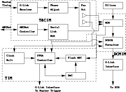
The first components that will be tested in the FEE test stand are the MVD
interface modules (the data collection interface module or DCMIM, the trigger
interface module or TIM, and the timing and control interface module or TCIM).
The interface modules are being designed at Oak Ridge National Lab. ORNL has
also developed an interface module testing scheme which will be used in our
test stand [ see
Nance's note]. The purpose of the test stand is to check the
functionalities of the interface modules.
At the time that we will have the interface
modules to test, we will still not have all the components which
compose the MVD read-out chain, like the PHENIX master timing and
trigger system, PHENIX data collection modules, and the MVD
multichip modules (MCM). All these components will be simulated with a
simple PC based system, so that we can test the functionalities
of the interface modules.
Below is the picture of the expected read-out chain including silicon detector, MCM, PHENIX standard modules (the DCM, master timer, master trigger), and the MVD interface modules. The dotted-line boxes delineate the TCIM, TIM and DCMIM.
