|

|

|

|

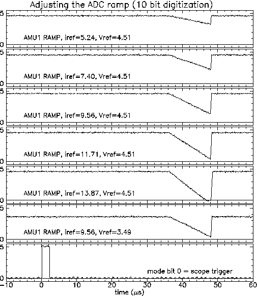
The first example shows the ramp with the ADCs set for 10 bit digitization. The 4X beam clock was 40MHz for this test. The test used the "Bench calibration" mode. This should not affect the shape of the ramp, but the scope is triggered on Mode bit 0, which initiates the bench calibration procedure. This trace is shown on the bottom. The other traces show various iref and Vref settings. A careful observer will notice that the length of the RAMP is too short for 10 bit digitization. The ramp should be 12.8 microseconds long (or slightly more). It actually seems to be 12 microseconds wide. The system seems to time out at about 120 beam clocks (12 microsec), rather than 200 beam clocks (20 microsec) as it should. Why it does this is an unresolved problem. It times out at the correct (200) number of beam clocks when we use a slower clock. The picture below is also available as a postscript file.

