|

|

|

|
DCIM clock signals -- Nov 14, 2000
Allan Hansen and John Sullivan
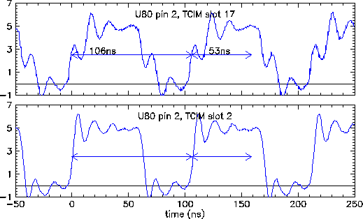
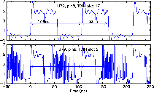
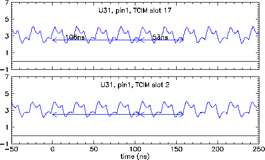
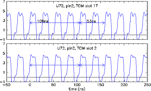
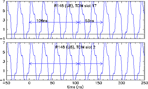
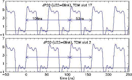
There are several older notes about studies of the clocks on the DCIM boards. Look here for a study on August 4, 2000. Look here for a study on October 4, 2000. The plots below were taken after we fixed a regulator on the TCIM board. They show a series of scope traces as the clock signals go through the DCIM board. We are still having some troubles with Glinks coming unlocked. We can see some problems in the intermediate clock signals on this board. However, the final result of the circuit -- the 40 mHz clock at the Xilinx chips and the 20 MHz clock at the Glinx chips look good. We can only assume that some of the unpleasant shapes of the clocks signals cause occaisonal "glitches" which in turn cause Glink failures. The two clock signals in each of plots show the signal with the TCIM board in slot 17 and 2 of the interface module crate. The DCIM board was in slot 21 in all cases.
In a few cases it was hard to trigger the scope on the right edge. This results in the bad scope traces seen in a few places.

