|

|

|

|
DCIM/TCIM clock signals
There is an older web page related to this one. It shows how the problems we have in generating a good "40 MHz" clock signal on the DCIM from the "10 MHz" clock are partly related to an offset in the input "10 MHz" clock, which translates to an unequal on/off duty factor for the "10 MHz" and therefore the "20 MHz" (intermediate clock).
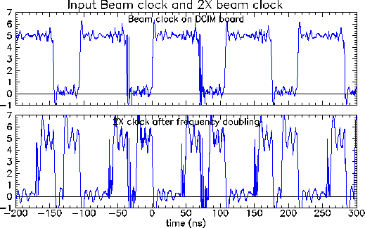
Today, while working on one DCIM we (Allan, Jan, Hubert, Fritz) saw a problem that Allan says he has seen on other DCIM boards. It is an extra "noise" pulse on the "20 MHz" clock. In this case it may or may not be related to an extra noise pulse on the input "10 MHz" clock. In the sample plots below, the 20 MHz clock always has an extra signal on the front edge of each pair of pulses. The 10 MHz clock (these are from the same scope trigger event) has a similar looking pair of pulses on the trailing edge of some of the pulses.
I am a little suspicious of the scope probes, but I think these are real problems. The output frequency after the frequency synthesizer is not 40 MHz -- it is about 60 MHz and slowly changes by 10 or 20% if you change the power supply voltage by 0.5 V or so. I think these "glitches" sometimes count as clock pulses and sometimes not.
Anyway, here are two pairs of plots showing the 10MHz clock and the 20 MHz clock. They show the same data plotted on two different horizontal scales.

