ps version
    1  +5V
    2  gnd
    3  out 1 = low-low
    4  out 2 = low
    5  out 3 = high
    6  out 4 = high-high
    7  analog out
    8-10 n.c
Hook it up, and read analog out; this is 5 mV/° in Kelvin. Therefore
1.49V is (1.49/0.005)-273.15 is 25°C
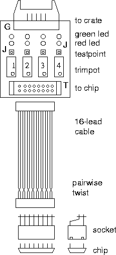
The trip points are set with the 4 pots. The set voltage is read on the little points just above. Clockwise is up.
The most important one is #4 ('high-high'), which is the one that trips the relay board. Choose a setpoint temperature, set the voltage on #4 by doing the conversion above. For the other points, I would choose some other temperatures, or just ignore them for now. As you cross the current temperature with the setscrew, the output line will switch between ~0V and 5V, and the led will go from green to red. That is, as the temperature rises across the setpoint, the voltage on the output line will go from 5V to0V.
Near 'T' is a testpin connected to the analog temperature, and 'G' is a ground test pin.
There are 2 jumpers J, which connect power and ground to the LED's and the driver chip. They can be removed after setup if the LED's draw too much power.