 |
 |
 |
 |
Temperature sensors on MCMs
Note!
1.white channels - used in 1st year, yellow channels - not used yet.
2.outputs from T-sensors are read through multiplexing ADCs on the Motherboard.
Below tables shows which T-sensor is going through which unit, which channel of
multiplexing ADCs.
more information about the multiplexing ADC
1. NW side
| - | MCM1 | MCM2 | MCM3 | MCM4 | MCM5 | MCM6 |
|---|---|---|---|---|---|---|
| G1 | U5,ch6 | U5,ch7 | U6,ch0 | U6,ch1 | U6,ch2 | U6,ch3 |
| G2 | U6,ch4 | U6,ch5 | U6,ch6 | U6,ch7 | U7,ch0 | U7,ch1 |
| G3 | U7,ch2 | U7,ch3 | U7,ch4 | U7,ch5 | U7,ch6 | U7,ch7 |
| G4 | U8,ch0 | U8,ch1 | U8,ch2 | U8,ch3 | U8,ch4 | U8,ch5 |
| G5 | U8,ch6 | U8,ch7 | U9,ch0 | U9,ch1 | U9,ch2 | U9,ch3 |
| G6 | U9,ch4 | U9,ch5 | U9,ch6 | U9,ch7 | U10,ch0 | U10,ch1 |
| G7 | U10,ch2 | U10,ch3 | U10,ch4 | U10,ch5 | U10,ch6 | U10,ch7 |
* Which group is which assembly?
G1 ----> Inner Top
G2 ----> Inner Middle
G3 ----> Inner Bottom
G4 ----> Outer Bottom
G5 ----> Outer Middle
G6 ----> Outer Top
G7 ----> pad
2.NE side;
| - | MCM1 | MCM2 | MCM3 | MCM4 | MCM5 | MCM6 |
|---|---|---|---|---|---|---|
| G1 | U5,ch6 | U5,ch7 | U6,ch0 | U6,ch1 | U6,ch2 | U6,ch3 |
| G2 | U6,ch4 | U6,ch5 | U6,ch6 | U6,ch7 | U7,ch0 | U7,ch1 |
| G3 | U7,ch2 | U7,ch3 | U7,ch4 | U7,ch5 | U7,ch6 | U7,ch7 |
| G4 | U8,ch0 | U8,ch1 | U8,ch2 | U8,ch3 | U8,ch4 | U8,ch5 |
| G5 | U8,ch6 | U8,ch7 | U9,ch0 | U9,ch1 | U9,ch2 | U9,ch3 |
| G6 | U9,ch4 | U9,ch5 | U9,ch6 | U9,ch7 | U10,ch0 | U10,ch1 |
| G7 | U10,ch2 | U10,ch3 | U10,ch4 | U10,ch5 | U10,ch6 | U10,ch7 |
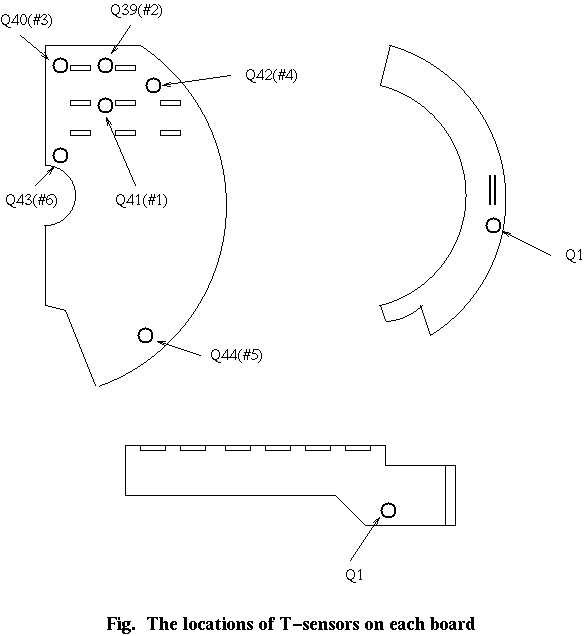
Temperature sensors on Motherboard and power/comm board
| - | #1(Q41) | #2(Q39) | #3(Q40) | #4(Q42) | #5(Q44) | #6(Q43) |
|---|---|---|---|---|---|---|
| MB | U11,ch0 | U11,ch1 | U11,ch2 | U11,ch3 | U11,ch4 | U11,ch5 |
*There are six temperature sensors per Motherboard.
| - | G1 | G2 | G3 | G4 | G5 | G6 | G7 |
|---|---|---|---|---|---|---|---|
| P/C | U11,ch6 | U11,ch7 | U12,ch0 | U12,ch1 | U12,ch2 | U12,ch3 | U12,ch4 |
*There is only one temperature sensor per power/comm board.

| - | U1 | U2 | U3 | U4 | U5 |
|---|---|---|---|---|---|
| ch0 | G1 5VD | G2 -5VA | G4 5VA COMP | G5 2.5VA | G7 5VA TGV |
| ch1 | G1 5VA COMP | G2 2.5VA | G4 5VA TGV | G6 5VD | G7 -5VA |
| ch2 | G1 5VA TGV | G3 5VD | G4 -5VA | G6 5VA COMP | G7 2.5VA |
| ch3 | G1 -5VA | G3 5VA COMP | G4 2.5VA | G6 5VA TGV | MB 5VD |
| ch4 | G1 2.5VA | G3 5VA TGV | G5 5VD | G6 -5VA | MB 5VA |
| ch5 | G2 5VD | G3 -5VA | G5 5VA COMP | G6 2.5VA | MB -5VA |
| ch6 | G2 5VA COMP | G3 2.5VA | G5 5VA TGV | G7 5VD | used for T-sensor |
| ch7 | G2 5VA TGV | G4 5VD | G5 -5VA | G7 5VA COMP | used for T-sensor |
Similar tables for analog spy are here.
last modified June-2-2000
by YoungGook Kim