Figure 2 shows the improvement in the CSC resolution when a Mathieson fit is used rather than a center of gravity fit. The upper plot shows the resolution across the width of a strip for the center of gravity fit, and the bottom shows the resolution for the Mathieson fit. As can be seen, the center of gravity fit does not give a flat resolution across the strip width, which is why we have used the Mathieson fit for our resolutions. If the resolution distributions are fit with a gaussian, the center of gravity fit produces a resolution which is 1.5 times worse than the Mathieson fit resolution.
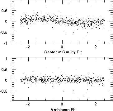
Figure 2: The CSC resolution versus the true position on
a strip for the center of gravity fit and the Mathieson
fit.
The CSC electronics specifications list 5000 electrons noise for our chambers [4]. The above input parameters give a total charge on the cathode strips on the order of 0.25 pico-Coulombs or 1.56E6 electrons. This makes a noise level of 5000 electrons equivalent to approximately 0.3% of the total charge. The CSC chamber resolution from the code for various noise levels, and the incident angles and Lorentz angle = 0 degrees is shown in figure 3.
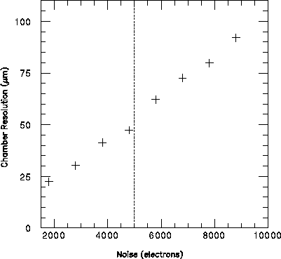
Figure 3: The CSC resolution versus various noise levels,
in electrons. All incident angles and the Lorentz angle
were set to zero. The baseline noise level is shown
with a dashed line.
If the cathode strips are perpendicular to the anode wires then the theta angle of incidence affects the CSC resolution only by the fact that the larger the angle is, the longer the path through the chamber is, so the total charge deposited in the chamber becomes larger. The larger total charge improves the signal-to-noise ratio, thus improving the chamber resolution somewhat. If the cathode strips are not perpendicular to the anode wires, then tracks which fire more than one anode wire (because of a non-zero theta angle of incidence) will create two anode charge distributions which are centered at two different places on the cathode strips. This will cause, at best, a charge distribution on the cathode strips which it is difficult to extract a correct centroid from. For these studies, we have assumed that the strips will be perpendicular to the wires and looked at the resolution as a function of theta. This is shown in Figure 4 where the chamber resolution versus the incident theta angle is shown, holding all other input parameters constant. The noise level for all points was 8800 electrons, the Lorentz angle was 0 degrees and the incident phi angle was 0 degrees.
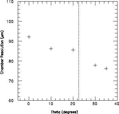
Figure 4: The CSC resolution versus various incident
theta angles, for 8800 electrons noise, 0 degrees
incident phi angle and 0 degree Lorentz angle.
The baseline average incident theta angle is
shown with a dashed line.
The angle of incidence in the x-z plane also affects the CSC resolution. If the track trajectory is not perpendicular to the anode wire, then the fluctations in the amount of ionization that occurs along the trajectory will affect how symmetric the charge distribution is along the anode wire (across the strips). The chamber resolution versus the phi angle of incidence is shown in Figure 5 where all chamber resolution affects have been turned off and the incident phi angle has been varied from 0 to 15 degrees. For our chambers, the angle of incidence will vary from +11.25 to - 11.25 degrees across each half of a chamber octant.
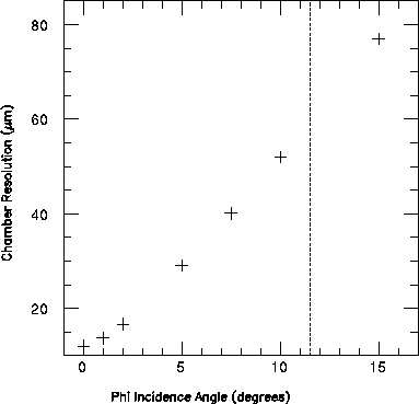
Figure 5: The CSC resolution versus various incident
phi angle ranges, for 0 electrons noise, 0 degrees
incident theta angle and 0 degree Lorentz angle.
The baseline average incident phi angle is
shown with a dashed line.
If the strips of the chamber are not perpendicular to the anode wires, then the charge distribution that is induced on the strips will shift, depending on where the incident track is in the space between the wires (or along the strips). In principle, this could be corrected for, if you know where the track is along the strips, but this requires some pattern recognition. (See Figure 6 where the simple correlation of the centroid position versus the distance between the anode wires is shown.) The affect on resolution, if it is not corrected for using pattern recognition, is shown from the simulations in Figure 7.
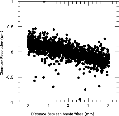
Figure 6: The uncorrected CSC resolution versus the position
between anode wires, when the strips are not
perpendicular to the anode wires.
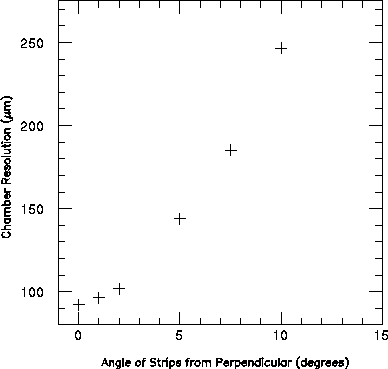
Figure 7: The uncorrected CSC resolution versus the strip angle,
where the strip angle is the difference between the
strip angle and the anode wire angle, minus 90
degrees. The noise level was 8800 electrons, and
the incident angles and Lorentz angle were 0 degrees.
The CSC resolution also is degraded by the Lorentz angle, which causes the electrons created in the chamber to follow a curved path as they drift to the anode wire. For our setup, the field is mostly radial, so the v(z) x B(r) curvature is what causes a skewing of the charge distribution in phi. For a fixed B-field, the CSC resolution versus Lorentz angle is shown in Figure 8. Note that for our baseline, we expect to have a Lorentz angle of roughly 8 degrees per 0.8 T and a maximum field of approximately 0.3 T, giving us a Lorentz angle of 3 degrees.
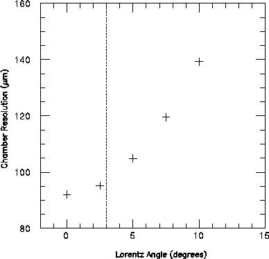
Figure 8: The CSC resolution versus various Lorentz
angles. The noise was 8800 electrons and the incident
angles were 0 degrees. The baseline Lorentz angle is
shown with a dashed line.
Finally, the CSC resolution depends on the strip width. If the strips are too wide, then the charge distribution will cover only a single strip or slightly more, making it difficult to extract a centroid. If the strips are too narrow, then the charge distribution begins to cover several strips, causing the signal to noise level on a given strip to be too small. The chamber resolution versus strip width is shown in Figure 9.
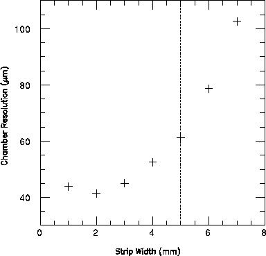
Figure 9: The CSC resolution versus various strip
widths. The baseline values for noise, incident angles
and Lorentz angle were used. The baseline strip width
is shown with a dashed line.
Taking all of these effects into account, the CSC simulation
was run with the baseline parameters listed in the previous
section and the resulting resolution is shown in Figure
10. We obtain a resolution of approxiamately
82  m. Note, however, that the angle of the
strips with respect to the anode wire was taken to be
90 degrees, which has not been the baseline CSC chamber.
We expect to either change the baseline so that the anode
wires will always be perpendicular to the cathode strips,
or use the pattern recognition to correct for the shift
of the charge distribution.
m. Note, however, that the angle of the
strips with respect to the anode wire was taken to be
90 degrees, which has not been the baseline CSC chamber.
We expect to either change the baseline so that the anode
wires will always be perpendicular to the cathode strips,
or use the pattern recognition to correct for the shift
of the charge distribution.
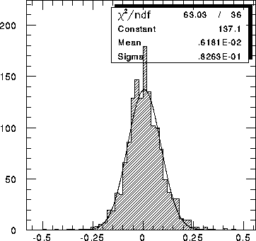
Figure 10: The CSC resolution for the baseline conditions
listed in the previous section.